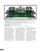
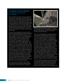
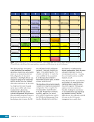
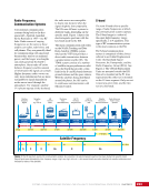
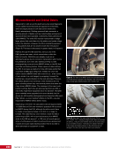
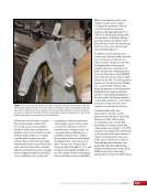
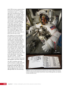
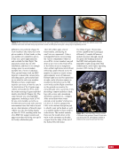
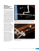
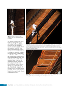
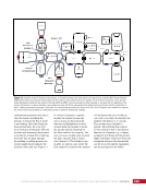
67 DAY IN THE LIFE: THE MAKING OF A MISSION CHAPTER 4 crew needed to be able to close the hatch to preserve crew members and the rest of the ISS. Therefore, these oxygen and water lines could not run through the hatchways. The lines are actually located within the aluminum structure of Nodes 1 and 3, passing through what is called the bulkhead. The required modifications to Node 3 were made prior to launch. However, for Node 1, this meant the crew had to make new holes in the port side, reroute the lines, reseal the bulkhead, and carefully check for leaks to ensure the integrity of the new seals. To perform the leak checks, the crew first needed to make the modifications and then measure for leakage on both sides of the seal. This was not possible without Node 3 in place. At that time, the other side of the wall of Node 1 was a vacuum. Per the initial mission plan, Node 3 would be installed and the crew would perform the modifications after the shuttle left. This meant, however, that the many hours needed to activate and outfit the module would have to be performed by three people—without the benefit of the seven extra astronauts that were available during a shuttle mission. The flight control team came up with an interesting proposal. A small connector module called the Pressurized Mating Adapter (PMA)3 resided on the ISS. Atlantis docked with PMA3 during the STS-98/ ISS-5A mission, but the module was not currently being used. This module could be moved by the robotic arm and installed on Node 1, thus providing a pressurized area in which to make the changes. The module would be moved back to its original location upon completion of the modifications. If the 120 hours of crew time could be found during the increment for this task, the modifications to Node 1 could be performed prior to the ISS-20A mission. This meant Node 3 could be connected and activated during the flight (i.e., “plug-and-play,” as the team called it) when those extra sets of hands are available. As with the change in the port location of Node 3, this had to be carefully coordinated and reviewed, especially since it meant taking the expedition crew away from research during the increment. However, a little investment in the time of the increment would significantly increase the larger shuttle crew’s efficiency. The more tasks completed during the shuttle mission, the less work for subsequent increments. This resulted in a net gain of increment time in which to focus on research. Many reviews and meetings later, the idea was given approval by the ISS Program. Originally, the modification hardware was to go up on 20A because it would be installed after the flight. With the new plan, the design, fabrication, and testing had to be accelerated to go up on an earlier shuttle flight. This proved to be a real challenge to the Boeing team members, but they worked extremely hard to pull this off. Another challenge discovered at this point was that the planned route of the power cables would be blocked as soon as Node 3 was installed. Therefore, the power cables had to be installed prior to the 20A mission. The STS-128/ISS-17A team members picked up this task because they had some spare EVA time. In 2008, the timeline leading to 20A changed to the following series of events: n During the interval following the second Japanese/American mission, STS-127/2 J/A, the ISS crew would move PMA3 from Node 1 nadir to Node 1 port using the station’s robotic arm n On STS-128/ISS-17A, the crew would route the power cables from nadir to port during an EVA n After STS-128/ISS-17A, some Node 1 modification work would begin if the parts could be accelerated to be ready in time n STS-129/ISS-Utilization Logistics Flight (ULF)-3 would bring up the remainder of the Node 1 hardware and finish most of the modifications n After ULF-3, the PMA3 would be relocated back to its pre-2 J/A location on the nadir of Node 1 by the ISS crew, again using the station’s robotic arm. n 20A crew would install Node 3 The 11-day mission now looked like this: n Launch the orbiter with Node 3 and Cupola n Install Node 3 on the ISS n Install ammonia lines, activate the module, and integrate the ammonia cooling into the system n Transfer critical items n Land the orbiter Finally, the following would be completed after the mission: n Relocate the Cupola from the end cap of Node 3 to its permanent nadir location n Relocate the life support systems into Node 3 and activate n Move the Advanced Resistive Exercise Device into Node 3 n Move the Treadmill 2 (T2) into Node 3
Purchased by unknown, nofirst nolast
From: Scampersandbox (scampersandbox.tizrapublisher.com)