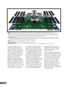
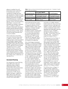
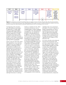
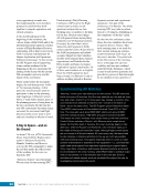
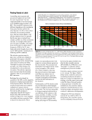
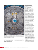
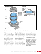
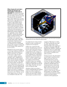
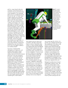
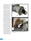
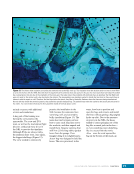
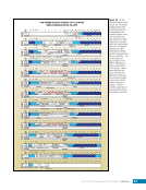
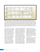
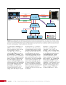
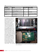
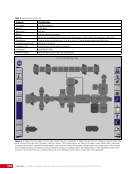
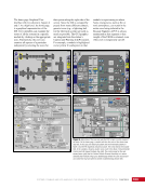
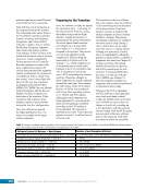
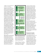
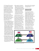
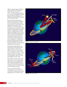
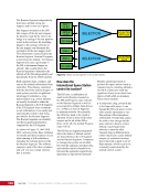
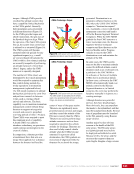
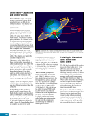
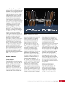
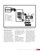
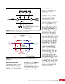
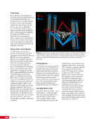
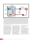
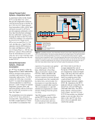
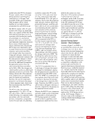
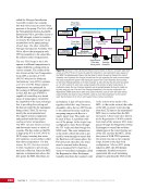
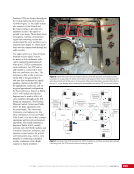
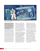
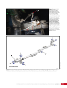
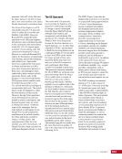
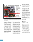
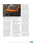
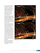
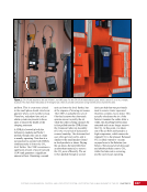
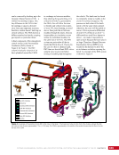
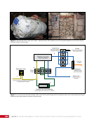
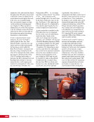
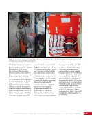
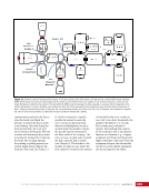
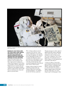
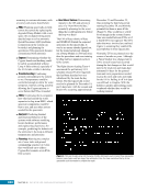
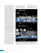
199 SYSTEMS: THERMAL CONTROL—THE “CIRCULATORY SYSTEM” OF THE INTERNATIONAL SPACE STATION CHAPTER 11 External Thermal Control Systems—Temperature Control As mentioned earlier in the chapter, FCVs are the three-way valves that provide temperature control in external thermal loops on the ISS. In the ETCS, the FCV must maintain loop temperature within a fairly tight tolerance (around 4°C [39°F]) to provide ammonia sufficiently cold to draw heat from the heat exchanger, but also sufficiently warm to avoid freezing the water on the ITCS side of the heat exchanger. In comparison, the PVTCS FCV simply moves all the way to return flow (i.e., full cool, also known as “open”) if the ammonia from the EPS batteries is too warm, and then moves all the way to bypass flow (i.e., full hot, also known as “closed”) when ammonia from the EPS batteries is too cool. Thus, the FCV in the ETCS has much finer control algorithms than the one in the PVTCS. External Thermal Control Systems—Pumps and Accumulators In a PVTCS, the pump is within the Pump and Flow Control Subassembly (PFCS), which provides ammonia circulation and control of the loop temperature and pressure. The PFCS contains the following: two pumps the FCV to control loop temperature a fluid accumulator to control loop pressure a suite of sensors to monitor temperature, pressure, flow, and ammonia quantity and an electronics unit to control all mechanisms on the loop. See Figure 5. Accumulator Pump Flow Control Valve Pump Pump and Flow Control Subassembly Radiator S4, P4, S6 or P6 Truss Cooled Ammonia Warmed Ammonia Ammonia Supply Nitrogen On-orbit Replaceable Unit Location on ISS Electrical System Hardware Figure 5. A simplified schematic of the PhotoVoltaic Thermal Control System. Redundant pumps (green) push cool ammonia (blue) to the electrical power generation and storage systems. The electrical systems are cooled by the ammonia absorbing the heat (red). The warm ammonia passes through a radiator where the heat is transmitted to space. The cooled ammonia (blue) returns to the Pump and Flow Control Subassembly to repeat the cycle. An accumulator maintains the pressure on the fluid line when the liquid expands or contracts as temperatures vary during an orbit around the Earth and throughout the year. A flow control valve allows mixing of warm and cool fluid to adjust the temperature of the loop. The accumulators serve two purposes in the PVTCS. Since ammonia is incompressible, rapid heating causes the fluid to expand quickly. If there is no method to accommodate that expansion, line pressures can quickly exceed the capacity of the fluid lines, which leads to burst lines. This is of particular concern in the PVTCSs, which were filled with ammonia coolant when launched, and were exposed to extreme thermal environments once they reached orbit but before they were activated. The first purpose is to provide room for ammonia to expand when it gets hot. The second purpose is to provide ammonia to compensate for a small amount of leakage from the system over time. The PFCS pumps in the PVTCS and the EETCS are run by a three- phase 120 volts (direct current) brushless pump motor and were set to operate at 13,580 revolutions per minute (rpm) to provide an average ammonia flow rate of 862 kg/hr (1900 lb/hr). The PVTCS are comparatively small and simple loops, with fairly short lines and no parallel flow paths, thus requiring much less pumping power than would ultimately be needed for the much larger and more complex ETCS. By comparison, the ETCS pump provides an average flow rate of between 3175 and 4309 kg/hr (7000 and 9500 lb/hr). The ETCS pump capacity is discussed later in this chapter. Each PVTCS and EETCS loop contains two identical pumps in case one fails. However, there is only one FCV per loop, since valves are generally more reliable than pumps.
Purchased by unknown, nofirst nolast
From: Scampersandbox (scampersandbox.tizrapublisher.com)