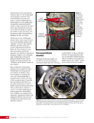
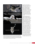
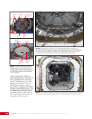
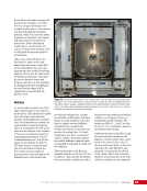
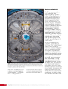
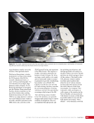
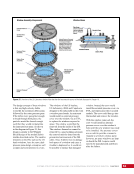
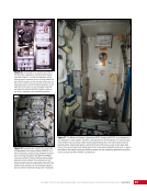
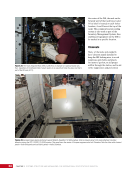
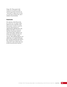
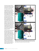
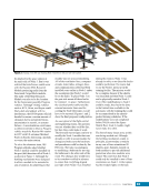
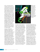
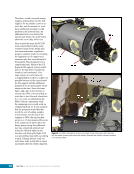
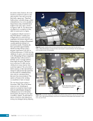
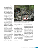
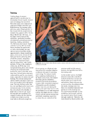
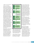
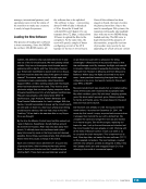
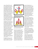
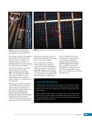
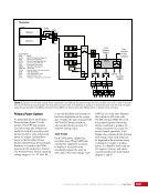
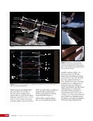
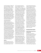
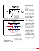
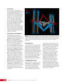
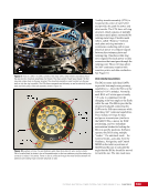
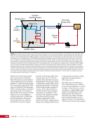
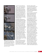
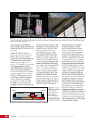
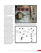
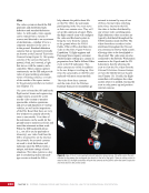
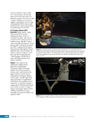
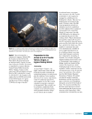
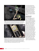
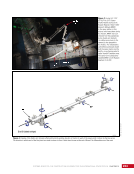
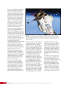
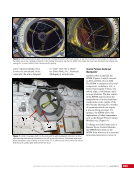
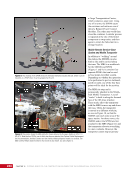
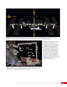
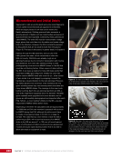
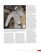
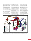
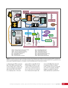
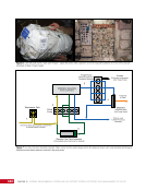
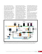
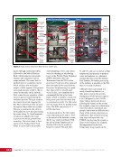
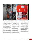
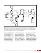
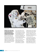
CHAPTER 11 SYSTEMS: THERMAL CONTROL—THE “CIRCULATORY SYSTEM” OF THE INTERNATIONAL SPACE STATION 202 The three-way valve in the heat exchanger assembly provides the ability to divert ammonia flow such that it bypasses the heat exchanger core. This valve is called a bypass valve (Figure 2). When the ETCS loop is off, this valve is adjusted to allow the ammonia flow to bypass the heat exchanger so that when the loop starts up, the super-cold ammonia will not be able to remove too much heat from the internal system. Although it sounds desirable to reject as much heat as possible, there is a point where things can get too cold. Because water expands as it freezes, the heat exchanger is not allowed to reach the freezing point of water. Otherwise, the frozen water will expand such that it ruptures the stainless steel parting sheet and then contracts as it thaws, leaving a hole for ammonia to leak through and into the cabin. An Isolation Valve—a two-way (i.e., two-position) valve that can be closed to isolate the heat exchanger core from ammonia flow— helps prevent the water from freezing in the IFHX. The ETCS ammonia is kept at a temperature of about 3.3°C (~37.9°F). If the temperature drops below that level, software in the system will automatically stop ammonia flow and configure these valves to bypass and isolate the ammonia side of the IFHX. When a heat exchanger is bypassed and isolated, it is hydraulically locked such that any sudden temperature increases within the ammonia will put the heat exchanger at risk of overpressurization. As another check to prevent overpressurization, the heat exchanger has a small ammonia fluid line, called a bleed line, which connects the ammonia inlet close to the heat exchanger core with the ammonia outlet outside the isolation valve. Some ammonia can escape through this line if pressure gets too high inside the isolated IFHX core. Heaters attached to the heat exchanger core and the water inlet and outlet lines are designed to prevent freezing of the water side of the heat exchanger. Additional safety checks in the ETCS software help detect issues and prevent the heat exchanger from freezing. The first response was detailed above: if the ammonia temperature drops to about 1.1°C (34°F), the ETCS pump will automatically shut down and the heat exchanger will be bypassed and isolated to prevent cold ammonia from entering the heat exchanger. The second and third checks monitor the quantity of fluid in the internal system pump accumulator. If the quantity of water measured in the accumulator begins to rise, the only source of fluid would be ammonia leaking into the water. Therefore, if the accumulator quantities in the ITCS go above a threshold, the pumps will be shut down to help prevent pushing ammonia into the cabin. As discussed in Chapter 19, the case of toxic ammonia leaking into the crew cabin is one of the three critical emergency events for which the crew and ground regularly train (see also Chapter 10). External Thermal Control Systems— Loads and Radiators The final component included in all the external thermal systems is the heat rejection point: the radiators. Although there are two types of radiators, they work the same way by providing radiative heat transfer from ammonia loops on the ISS. One type is known as a PhotoVoltaic Radiator (PVR), which is installed in the eight PVTCSs. The second type is known as the Heat Rejection Subsystem (HRS) or, more commonly, the ETCS radiators. Both types of radiators consist of a base panel connected to a series of radiator panels that are hinged together, accordion-style, such that they can be deployed (i.e., straightened out, end to end) or retracted (folded back together, face to face) (Figure 7). Each radiator was fully retracted at launch and has an automated deploy/ retract capability with a manual override that can be controlled by a spacewalking astronaut. The P6 truss segment houses a total of three radiators. One radiator, known simply as the 2B/4B PVR, faced forward to be shared between the two PVTCS loops. The remaining two radiators were shared between the two EETCS loops. One radiator faced aft and therefore is still known as the Trailing Thermal Control Radiator (TTCR). The other radiator faced starboard in the original P6 location, and is known as the Starboard Thermal Control Radiator. Note: Now that the outboard truss segments rotate 360° to support solar array pointing, neither name is accurate. See also Figure 4. The PVR radiator type is always shared between two independent loops and has seven radiator panels. The seven panels together can reject from 9.5 to 14 kW of heat, depending on the thermal environment. This is equivalent to the capacity of the air conditioner in an average house in the southern United States. The inside of each radiator panel is a honeycomb made from aluminum sheeting, with that honeycomb sandwiched between two 0.254 mm (0.010 in.) sheets of aluminum that are then coated with either silver or white coating to ensure optimal reflectivity. Each panel has 24 stainless steel tubes that measure 0.17 cm (0.067 in.)—12 tubes for
Purchased by unknown, nofirst nolast
From: Scampersandbox (scampersandbox.tizrapublisher.com)