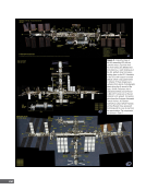
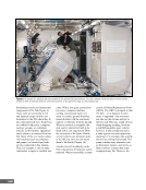
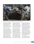
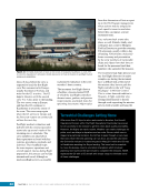
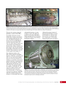
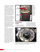
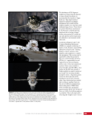
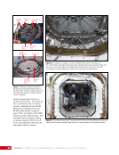
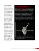
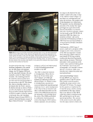
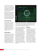
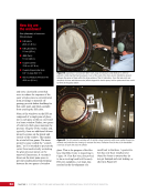
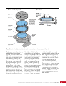
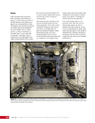
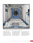
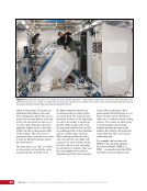
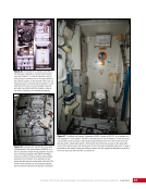
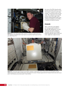
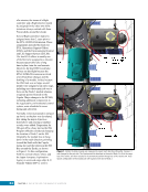
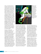
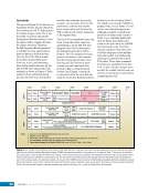
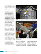
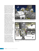
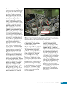
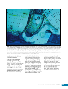
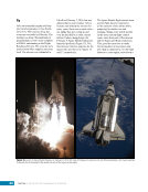
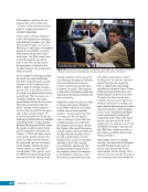
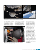
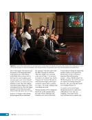
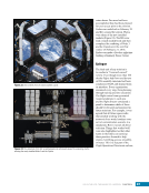
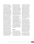
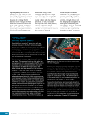
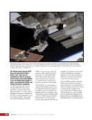
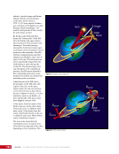
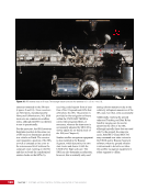
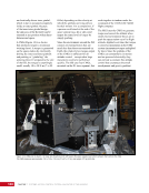
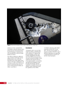
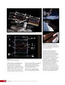
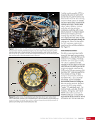
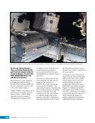
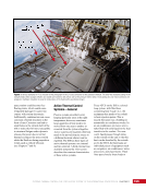
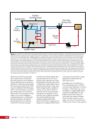
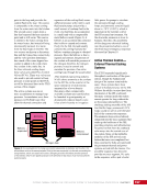
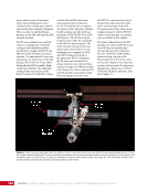
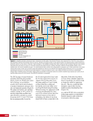
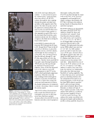
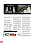
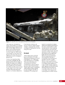
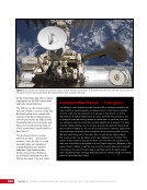
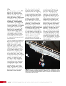
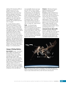
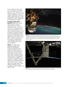
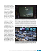
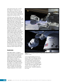
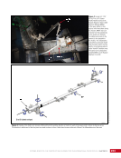
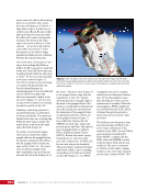
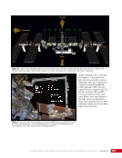
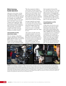
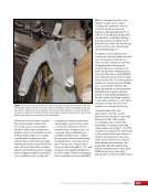
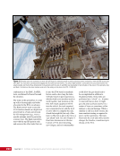
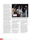
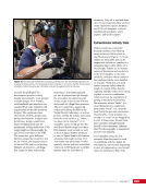
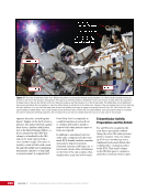
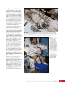
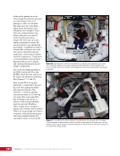
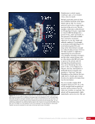
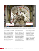
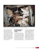
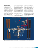
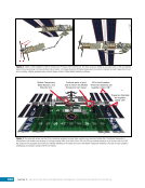
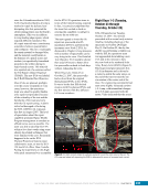
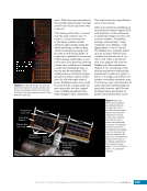
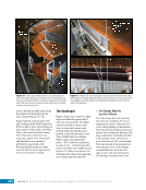
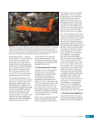
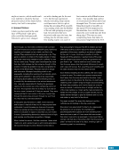
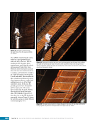
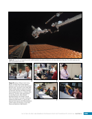
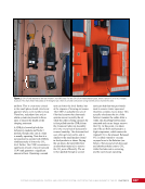
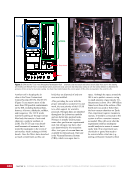
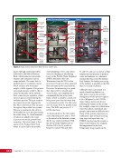
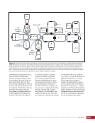
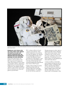
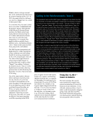
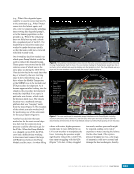
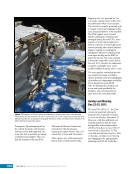
41 SYSTEMS: STRUCTURE AND MECHANISMS—THE INTERNATIONAL SPACE STATION’S SKELETON CHAPTER 3 A vestibule is created between the two hatches when the two modules are connected. This is just like a vestibule between two train cars. In this vestibule area, the astronauts connect gas (e.g., oxygen, nitrogen, air), water, data, and electrical lines between the two modules. All of these utilities are connected inside the pressurized area of the vestibule but outside of the hatchway itself. This means the utility lines can be connected without an EVA, but the lines will not run across the open hatchways of the modules. For an example, see Figures 8 and 9. This configuration enables the crew to close the hatches quickly to isolate a module in an emergency, should it be required. The CBM not only connects the permanent US Segment modules during ISS assembly, it is also used to connect US cargo vehicles (e.g., H-II Transfer Vehicle [HTV], Dragon, and Cygnus) when they arrive. These cargo vehicles use the CBM interface because it provides capability for transfer of both small cargo bags and large hardware such as racks between the cargo vehicle and the ISS. Crewed vehicles use smaller docking systems because large hardware does not need to transfer between the crewed vehicles and the ISS. Docking mechanisms can also release the docked spacecraft faster than vehicles connected by CBM. Each CBM location can be operated multiple times, if needed. This capability enables cargo vehicles to be attached and detached from CBM locations dedicated to cargo operations. That CBM capability also means that permanent ISS modules can be detached and relocated to alternate CBM locations, if needed. The Manual Berthing Mechanism The early ISS assembly sequence had the Pressurized Mating Adapter (PMA)2 docking adapter on the front of Node 1. The Space Shuttle brought the US Laboratory to the ISS on STS-98/ISS-5A (2000). The orbiter docked to PMA3, located on the bottom (nadir) side of Node 1. The astronauts needed to remove PMA2 from the front of Node 1, put PMA2 somewhere, install the US Laboratory on the front of Node 1, and then put PMA2 on the front of the US Laboratory. To make this happen, an additional CBM location was required to temporarily store PMA2 while the US Laboratory was being installed. This need was realized early in the ISS design development therefore, a manually operated CBM that used only latches (i.e., the Manual Berthing Mechanism (MBM]) was added to the front side of the Z1 truss (Figure 10). This enabled the astronauts to move PMA2 to this Z1 location and house it there temporarily while the US Laboratory was being installed. The spacewalkers then released PMA2 from the MBM and moved it robotically to the front of the US Laboratory. The MBM, while still in place on the front of the Z1 truss, fulfilled its job during that mission and has not been used since. Figure 10. Photo of the ISS as STS-92/ISS-3A (2000) departed, showing the Z1 truss on top of Node 1 with the large ring of the MBM on the front of the truss. The round and square targets in the middle of the MBM are Space Vision System targets. The Space Vision System is discussed in more detail later in this chapter.
Purchased by unknown, nofirst nolast
From: Scampersandbox (scampersandbox.tizrapublisher.com)