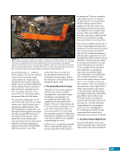
159 SYSTEMS: ELECTRICAL POWER SYSTEM—THE POWER BEHIND IT ALL CHAPTER 9 controllers (small computers) that interface with the Command and Data Handling system to provide data and receive commands. These firmware controllers monitor current, voltage, and temperature sensors to provide insight into the health and function of the EPS. They also respond to commands from ground controllers, crew members, or automated software functions on board. These commands can open or close switches, turn automated functions on or off, or change the modes or set points that manage EPS operations. One downside is that the system had an increased dependence on computers to safe hardware. This is especially evident when certain computers control their own power switches. If one of those computers malfunctions, it may be necessary to go farther upstream in the EPS to remove power from the faulty computer, thus impacting other user loads. In fact, a significant part of a module may need to be powered down to change out the faulty computer. Although remote-control capabilities have proven beneficial for freeing up crew time and potentially saving the ISS if a crew is not available to respond to off-nominal situations, having practically no manual overrides in the EPS also has its detriments. System Overview Power Channels The USOS EPS is divided into eight power channels: 1A, 1B, 2A, 2B, 3A, 3B, 4A, and 4B. A power channel contains the equipment necessary to generate, store, and distribute power as an independent source. It also contains support equipment for command and control, cooling, and solar array pointing to keep the power channel functioning. The primary power equipment responsible for generating and storing electrical power is located on four Photo- Voltaic Modules (PVMs): the P4, P6, S4, and S6 truss segments. Each PVM supports two power channels. Hardware for channels 1 and 3 is located on the starboard truss hardware for channels 2 and 4 is located on the port truss. The two fully independent and redundant power channels are labeled A and B. Channel A runs on S4 and P4, whereas B is connected to S6 and P6 (Figure 1). 3B 1A 1B S6 S4 P4 P6 4A 2B 2A 3A 4B Assembly Complete US EPS 8 power channels (1A, 1B, 2A, 2B, 3A, 3B, 4A, 4B) 4 photovoltaic modules (S6, S4, P4, P6) Power Channel Naming Convention Odd numbers are starboard, even numbers are port A panels are inboard, B panels are outboard Figure 1. ISS PVMs and power channels. A subset of power channels—1A, 1B, and 2B—are considered to be the core power channels. These channels provide power to some of the most important space station systems hardware such as critical avionics (e.g., computers and communications equipment), life support systems, and external and internal Thermal Control Systems. These core channels and the concept of electrical power domains greatly impact how redundancy of critical systems was designed and is maintained on the ISS. Operationally, it is important to note that these critical systems are unevenly distributed across these core channels. Channel 1A supports ETCS Loop A, while channel 1B powers one string of critical avionics. However, channel 2B alone supports ETCS Loop B and one string of critical avionics. Due to this uneven distribution, loading on channel 2B is higher than the other core channels and takes more planning to keep it within energy balance when the ISS is in a power- constrained configuration, such as one that occurs during vehicle dockings (e.g., requiring a solar array to be in a fixed position). Domains and Redundancy Even with the best designs, ISS hardware and systems can wear out and fail. Critical systems have backups and sometimes multiple backups to keep the space station
Purchased by unknown, nofirst nolast
From: Scampersandbox (scampersandbox.tizrapublisher.com)


