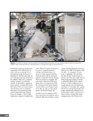
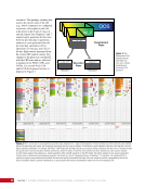
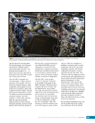
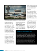
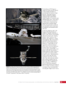
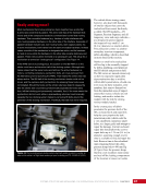
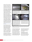
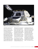
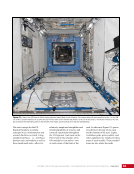
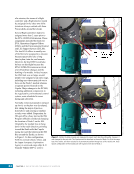
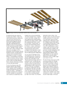
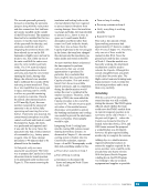
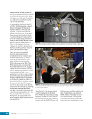
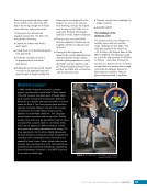
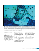
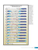
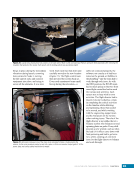
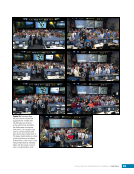
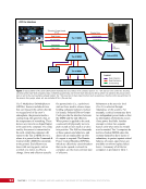
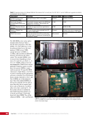
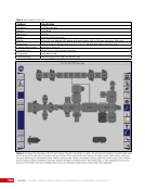
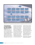
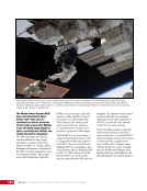
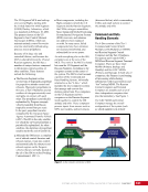
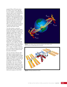
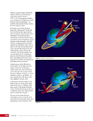
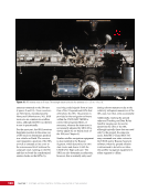
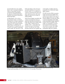
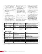
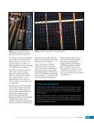
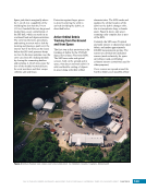
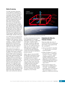
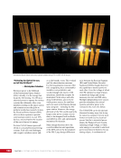
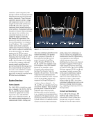
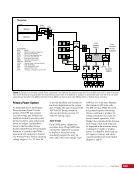
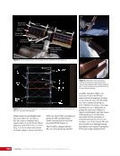
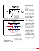
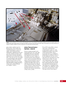
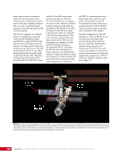
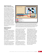
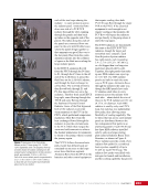
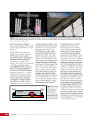
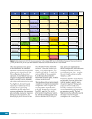
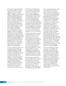
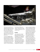
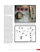
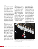
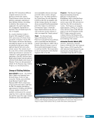
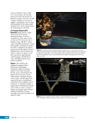
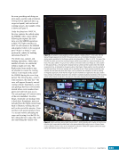
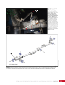
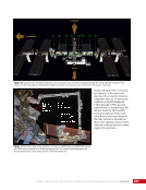
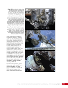
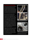
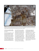
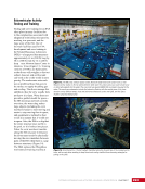
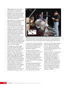
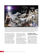
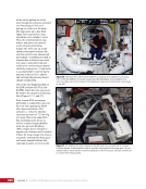
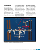
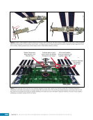
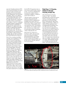
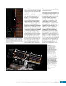
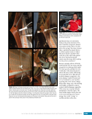
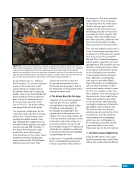
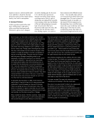
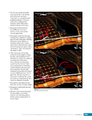
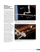
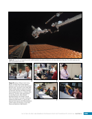
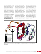
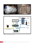
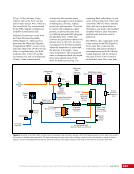
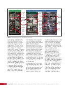
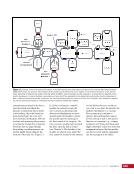
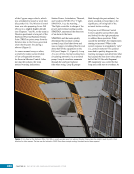
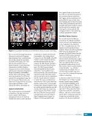
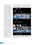
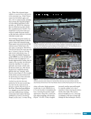
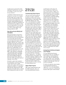
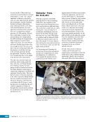
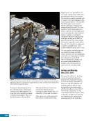
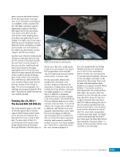
203 SYSTEMS: THERMAL CONTROL—THE “CIRCULATORY SYSTEM” OF THE INTERNATIONAL SPACE STATION CHAPTER 11 each of the two loops sharing the radiator—to carry ammonia across the radiator panel. Ammonia flows down one side of a PVR/TCR radiator through the tubes running through the panels and then back up tubes on the opposite end of the panels. The tubes along the ends of the panels are connected from one panel to the next with flexible hoses where the panels hinge together so that ammonia can get all the way to the last panel. Heat from the warm ammonia radiates into the coldness of space as the fluid moves along the large radiator panels. Figure 7. Deployment of the PhotoVoltaic Radiator on the P3 truss during STS-115/ISS- 12A in September 2006. The sequence from top to bottom shows the radiator unfolding from the compact launch configuration to its fully extended length, approximately 12.53 m (~493.4 in.). Each of the seven radiator panels is approximately 3.12 x 1.79 x 0.02 m (~124 x 70.6 x 0.69 in.), or about the size of two queen-sized mattresses placed next to one another. In the EETCS, ammonia flowed from the PFCS through the P6 lines to Z1, through the Z1 lines to the aft end of the LAB where it joined the fluid lines on the LAB Aft Endcone, and through the heat exchanger to collect heat. The warmed ammonia then flowed back through Z1 and P6, this time all the way up to the radiators. The flow from each EETCS loop split, some flowing through the TTCR and some flowing through the Starboard Thermal Control Radiator. Some of the flow bypassed both of the radiators to provide warm ammonia to the FCV in the PFCS, which performed temperature regulation. Most flow from the heat exchanger flowed through the radiators to provide cold ammonia to the FCV, which then merged the warm and cold ammonia to achieve the desired temperature for ammonia to return to the pump, where it started the journey again. The PVTCS follows the same basic path, except that all heat loads are contained on one truss so the loops never leave that truss segment. Ammonia flows from the PFCS to the batteries and other control equipment that require cooling, then both PVTCS loops flow through the single PVR to the PFCS. If the electrical equipment is cool enough to not require cooling at that moment, the FCV flow will bypass the radiators and go directly to the pump where it starts the loop again. The ETCS radiators are functionally the same as the EETCS/PVTCS radiators, though far larger and somewhat more complex. Each Heat Rejection System radiator has eight panels, each measuring 3.4 x 2.7 m (131.25 x 107.00 in.), or a bit bigger than two king-size mattresses placed side by side. Together, the eight panels that make up one HRS radiator can reject up to 11.67 kW. The HRS radiator panels are built in much the same way as PVR types. Ammonia flows through the radiators the same way, though the HRS panels have only 22 stainless steel tubes to carry ammonia across the radiator with each tube—about double the size of those in the PVR radiators at 0.32 cm (0.13 in.) in diameter. Each HRS radiator is used by only one ETCS loop, but each has two independent flow paths, thus allowing some flexibility of cooling capability. The 22 tubes that run across each radiator panel are distributed between the two independent flow paths in an alternating pattern. Each ETCS loop has three HRS radiators installed side by side on a large rotating plate called a Radiator Beam Truss Structure, as shown in Figure 8. Three radiators provide a total of six radiator flow paths for a combined heat rejection capability of up to 35 kW for each ETCS loop. The radiator flow paths were filled with nitrogen for launch and installation, and the cooling capability has proven
Purchased by unknown, nofirst nolast
From: Scampersandbox (scampersandbox.tizrapublisher.com)