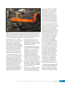
CHAPTER 3 SYSTEMS: STRUCTURE AND MECHANISMS—THE INTERNATIONAL SPACE STATION’S SKELETON 44 Finding Ready to Latch Assembling truss segments and pressurized modules all start with the same requirement—the new component needs to be close enough to its intended mating location to be RTL. The actual RTL indicators look different depending on the mechanism being used, but they perform the same function. The RTLs move when touched by the incoming module/ truss. This movement signals to the robotics operators (crew or ground) that the new piece is indeed close enough, and that use of the mechanism can start. An example of this can be seen in Figure 6 (middle). This image from STS-92/ISS-3A (2000) shows the passive CBM of the Z1 truss being robotically brought close to the active CBM of Node 1 Zenith prior to achieving an RTL condition. The robotics operators need to know how well the new element is positioned with respect to the ISS mechanism prior to the element being at the point of touching the RTLs. Although the trusses and modules are large, very little tolerance for misalignment is allowed between two pieces. The robotics operators must precisely align the incoming element so that it can touch those RTL indicators. Realizing this critical need for assembly of the ISS in orbit, engineers designed a computer-generated Space Vision System (SVS). The SVS was an optical system that used computer evaluation of camera views to precisely determine the misalignment between the ISS and the new component. Myriad SVS targets— decals with white and black dots (visible in Figure 10)—were installed on modules and truss segments. Prior to launch, the placement of these targets was measured precisely with respect to various reference points on the truss/module. This measurement information was loaded into the vision system computers of the robotic arm. These computers, knowing the precise location of the targets, could then use camera views to identify specific targets, precisely compute misalignment information, and provide that information to the operators. Unfortunately, an SVS solution could only be obtained in orbital daylight (which is roughly 45 minutes or less of every orbit). The SVS was susceptible to losing an acquired solution due to sun reflection off the surfaces of the trusses, modules, or orbiter, or if the targets were obscured by shadows. NASA successfully used the SVS during early stages of ISS assembly however, the agency decided soon after the first assembly mission (STS-88/ISS-2A [1998]) that a new “boresight” or centerline camera misalignment system was needed. Centerline camera systems were not a new concept. The Space Shuttle always used a centerline camera on its docking mechanism window to help crews make final alignments for docking to the Mir space station and to the ISS. Space Station Freedom, a design precursor to the ISS, also included use of a centerline camera mounted on the ISS hatches to view incoming modules through the hatch windows to determine misalignments. 9 8 7 6 5 4 3 2 1 0 0.0 0.5 1.0 1.5 2.0 2.5 3.0 3.5 4.0 Roll Angle (deg) Roll vs. Translation to Ensure Proper Guide Meshing Risk of Mis-meshing Proper Meshing PCBM ACBM X Y Lateral Offset (in.) FLIGHT RULE B12-111, PARAGRAPH A: During mating operations, when between 14 inches and 6 inches X-distance separation, the roll and lateral misalignments shall ensure 9R+20L 73 (depicted in diagram below). If this constraint is not maintained, the operator must separate the PCBM and ACBM rings. The operator should back out in the X direction until 14 inches of separation is met, or the corridor is reattained. Figure 11. A portion of Flight Rule B12-111 “CBM Capture (RMS Translation) Corridor Constraints” that explains to the flight controllers how wobble (i.e., a combination of roll and lateral offsets) must be controlled to ensure the CBM halves are properly aligned at the RTL position. Meshing occurs when the CBM halves are separated between 15 cm and 35.5 cm (6 in. and 14 in.). The lateral offset can range between 0 cm and 10 cm (0 in. and 4 in.). Although the SVS was ultimately selected for use with the ISS in its design phase, the centerline camera was not completely removed from all
Purchased by unknown, nofirst nolast
From: Scampersandbox (scampersandbox.tizrapublisher.com)


