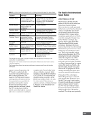
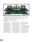
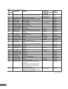
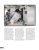
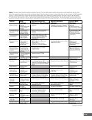
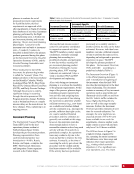
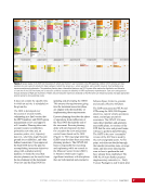
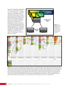
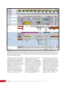
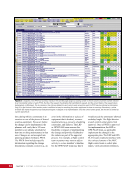
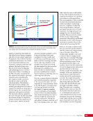
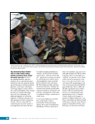
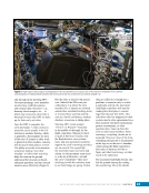
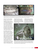
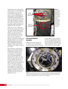
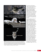
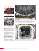
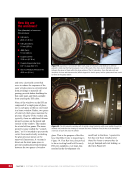
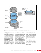
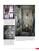
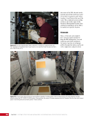
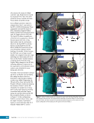
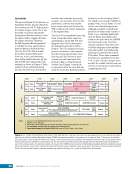
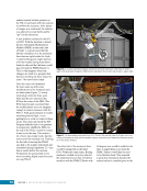
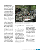
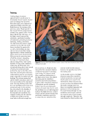
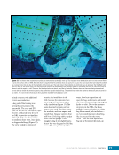
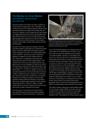
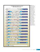
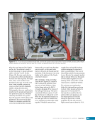
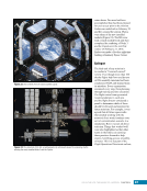
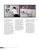
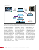
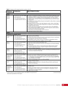
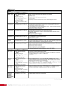
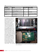
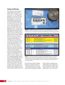
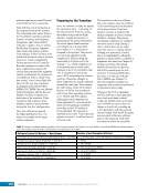
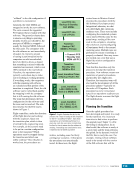
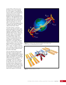
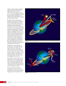
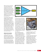
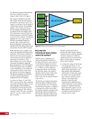
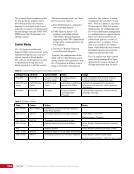
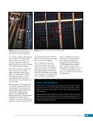
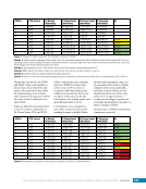
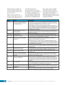
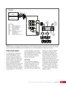
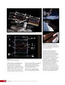
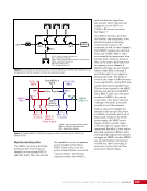
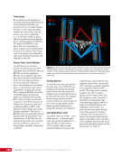
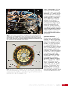
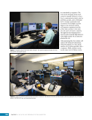
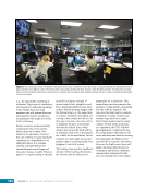
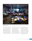
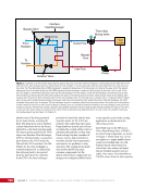
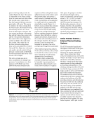
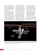
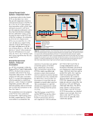
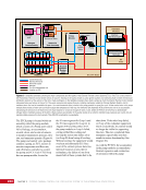
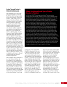
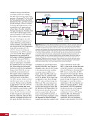
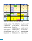
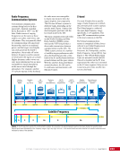
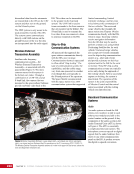
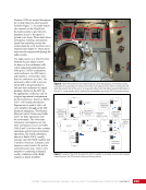
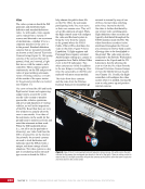
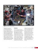
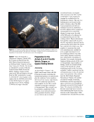
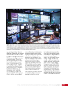
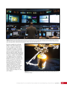
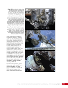
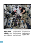
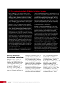
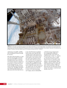
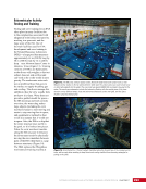
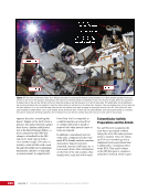
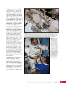
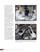
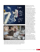
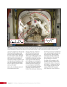
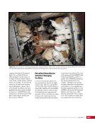
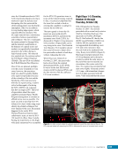
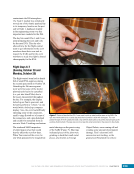
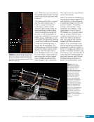
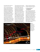
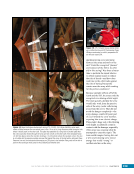
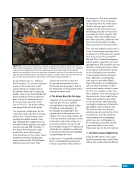
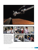
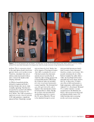
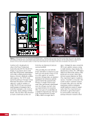
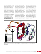
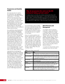
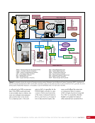
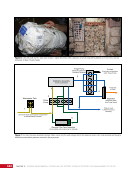
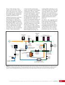
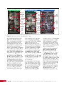
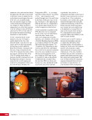
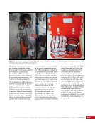
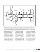
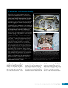
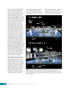
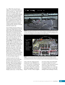
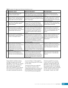
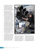
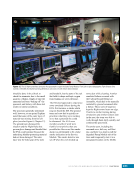
99 SYSTEMS: COMMAND AND DATA HANDLING—THE BRAINS OF THE INTERNATIONAL SPACE STATION CHAPTER 5 (PL)—come with additional memory storage. Initially, this storage was in the form of a 300 MB Mass Storage Disk (MSD). This was actually a spinning magnetic disk commonly found in most desktops. In 2001, Solid State Mass Memory Units (SSMMUs) with 2 MB flash memory cards replaced the disks. A High Rate Data Link card provides the interface to the MSD/SSMMU. Since sensors come in a variety of types (e.g., analog, digital), the Tier 3 MDMs contain a number of I/O computer cards that transmit the data. The measurement of temperature or voltage are examples of analog data in that the sensor will read the value (e.g., 15.3ºC [59.5ºF]) and transmit that number to the computer. Data that are discrete in that they report binary data use digital cards. Of course, even the analog data are sampled and digitized—like music is sampled and digitized on a compact disc—so that the data may easily be transmitted to the ground. These cards are summarized in Table 3. When Computers Crash The C&C and PL MDMs were launched in 2001 with MSDs. Primary use for the disk was to store the operating software that could not fit into the nonvolatile memory. The C&C MSD also functioned as a telemetry recorder for later playback when the ISS was out of communication with the ground, as well as a staging place for uplinking or downlinking data files. NASA accelerated a planned upgrade to newer SSMMUs in the summer of 2001 after the hard drives on all three C&C MDMs failed during the Space Transportation System (STS)-100/ISS-6A mission due to damage on the delicate surface of the disks. In 2004, the CCS software was redesigned to fit as a zipped file in nonvolatile memory so that the system could almost always boot up for most failures. In the initial design, display data needed for the crew’s PCS displays resided as files on the C&C MSD, which were transferred over when the crew activated that display. However, these displays would not work with a failed MSD, so they were moved to spare memory of the High Rate Data Link card. When the MSDs failed during and after STS-100/ISS-6A, identical units from the PL MDMs were removed, installed into the C&C MDMs, and reformatted. The CCS software was then completely reloaded onto the drives. Table 3. Summary of Standard MDM Card Properties Input/Output Card Typical Use Number of Channels Number of Cards on the International Space Station Low-level Analog Reads analog voltage or supplies the current source to measure the drop across a Resistive Temperature Device. Mainly used for precise temperature measurements. 32 57 High-level Analog Reads analog sensors (pressure, flow rate, speed). 32 24 Analog Input/Output Drives analog effectors (valves and switch positions) and reads voltages. 16 22 Digital Input/Output Reads discrete sensors (valve and switch positions). 32 54 Solenoid Driver Output Activates and deactivates solenoids and valves. 16 26 MDMs communicate over a network of busses that consist of twisted copper lines using the Military Standard 1553 communication protocol. This protocol may be a bit old, but it is well tested and robust, and has been used on aircraft and military ships. Originally, the design of the Space Station Freedom, which was to use as much groundbreaking technology as possible, called for a fiber-optic computer network. However, when this proved too costly, copper cables that did limit data transfer rates were adopted. The copper wire busses actually consist of two separate-but-identical cables called channels. If an MDM is having trouble talking to another device on one channel, the system will switch to another channel and try talking to that channel. Each channel’s wire is also physically separated from the others.
Purchased by unknown, nofirst nolast
From: Scampersandbox (scampersandbox.tizrapublisher.com)