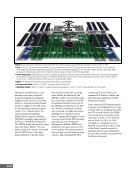
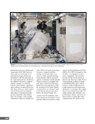
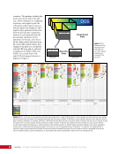
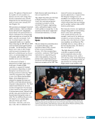
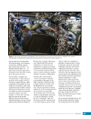
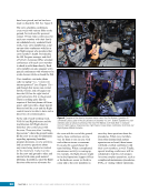
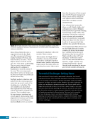
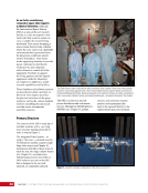
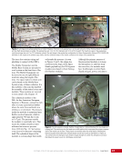
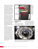
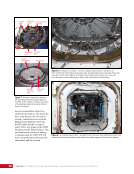
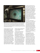
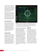
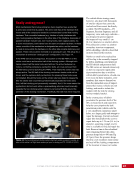
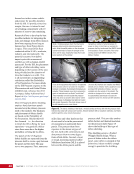
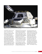
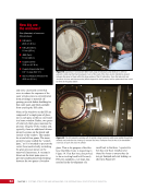
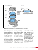
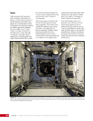
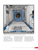
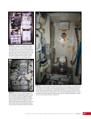
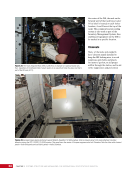
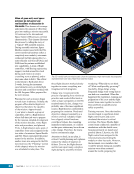
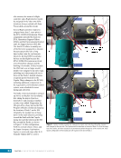
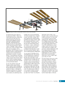
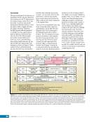
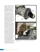
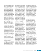
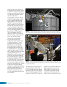
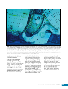
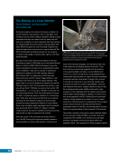
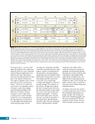
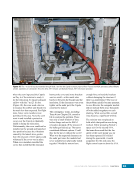
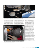
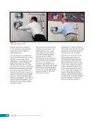
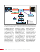
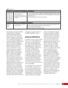
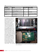
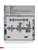
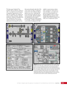
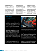
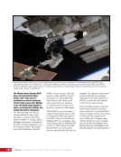
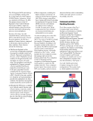
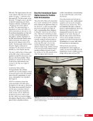
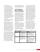
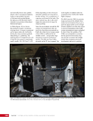
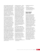
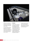
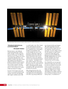
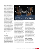
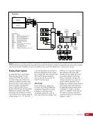
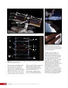
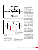
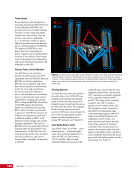
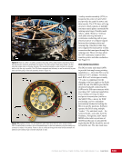
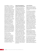
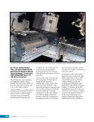
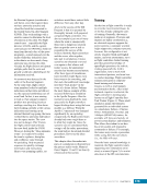
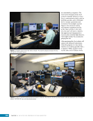
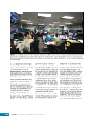
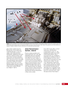
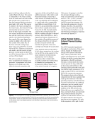
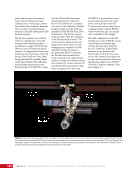
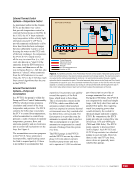
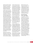
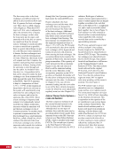
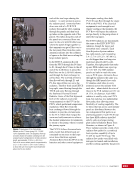
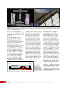
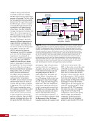
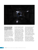
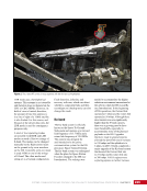
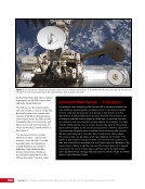
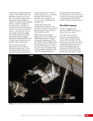
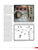
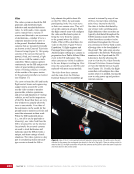
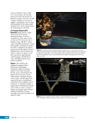
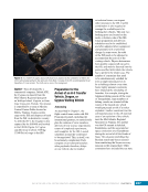
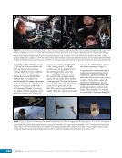
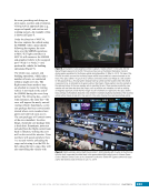
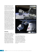
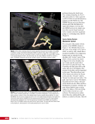
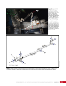
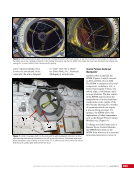
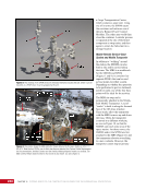
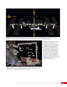
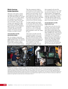
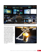
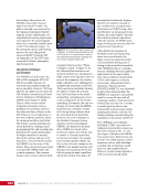
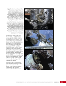
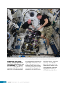
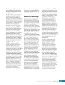
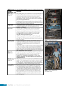
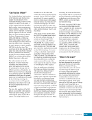
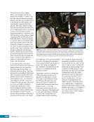
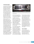
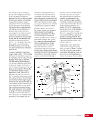
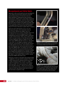
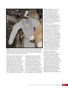
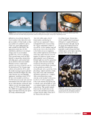
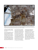
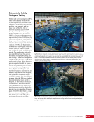
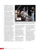
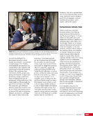
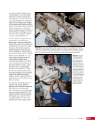
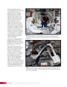
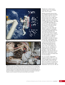
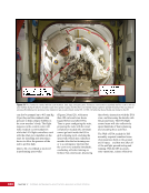
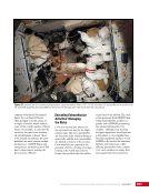
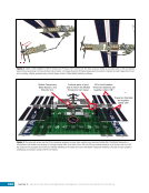
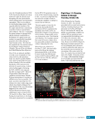
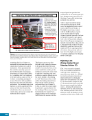
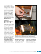
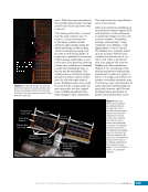
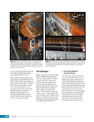
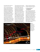
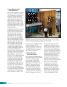
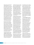
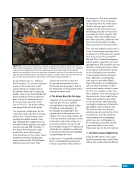
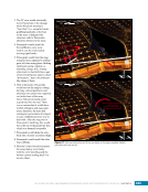
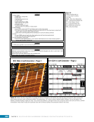
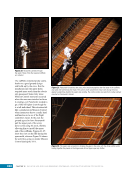
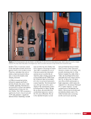
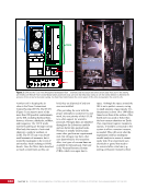
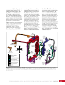
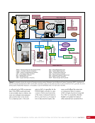
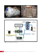
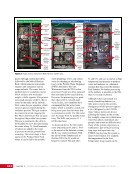
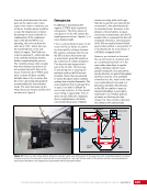
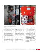
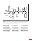
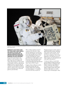
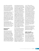
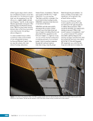
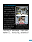
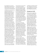
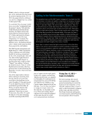
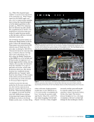
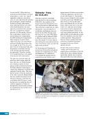
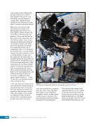
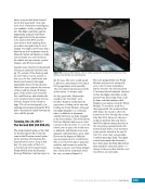
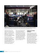
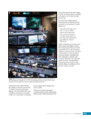
CHAPTER 3 SYSTEMS: STRUCTURE AND MECHANISMS—THE INTERNATIONAL SPACE STATION’S SKELETON 40 mid-size automobiles stacked on each bolt/nut location. This keeps the three seals between the two halves securely compressed even with the high pressure difference between the ISS cabin and the vacuum of space. Three seal beads on the CBM interface provide fault tolerance. One seal bead can be scratched, leaking, or damaged and the CBM will still have two good barriers between the atmosphere and the vacuum. Capture Latch Passive Nut Alignment Guide Passive Structural Ring Capture Latch Fitting Alignment Guide Controller Panel Assembly Structural Ring Powered Bolt Figure 7. Hardware component breakdown of the active (top) and passive (bottom) halves of the CBM. An RTL indicator is situated next to four of the alignment guides on the active CBM (not shown in the figure). Figure 8. An example of a vestibule. This is the vestibule between Node 1 and Node 3 on STS-130/ISS-20A (2010) before all the power, data, and fluid jumpers were connected. Power and data cables for the active CBM are still installed (seen floating) but no jumpers are connected yet to the large or small feedthroughs on Node 3 (the module with the closed hatch). Figure 9. The vestibule between Node 1 and Node 3 after it has been fully outfitted and a white cloth closeout barrier has been installed to keep objects from getting trapped or lost inside the vestibule.
Purchased by unknown, nofirst nolast
From: Scampersandbox (scampersandbox.tizrapublisher.com)