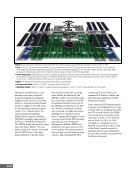
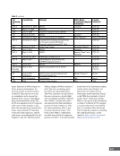
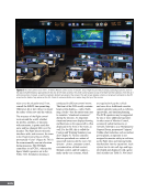
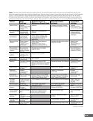
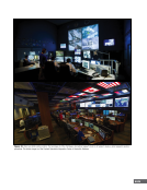
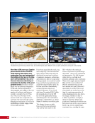
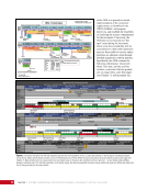
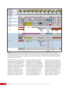
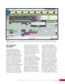
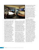
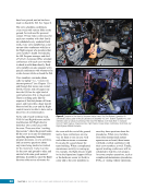
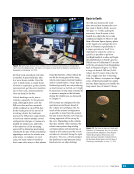
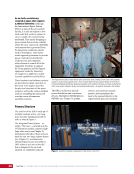
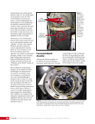
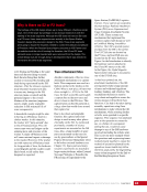
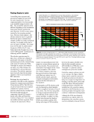
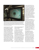
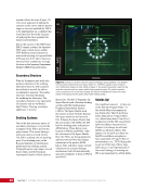
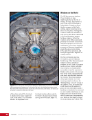
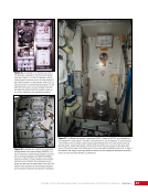
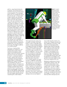
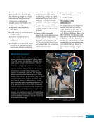
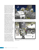
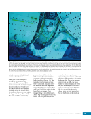
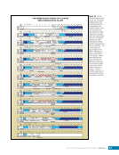
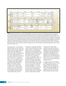
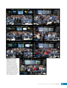
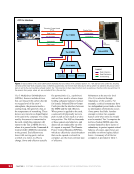
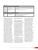
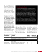
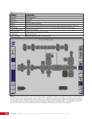
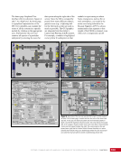
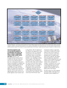
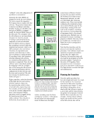
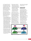
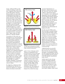
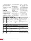
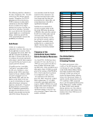
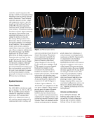
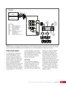
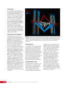
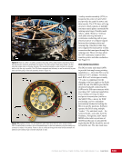
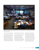
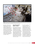
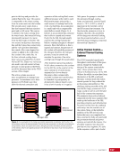
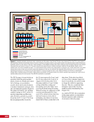
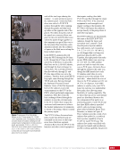
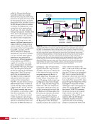
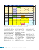
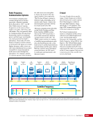
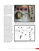
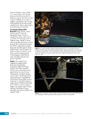
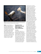
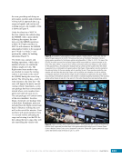
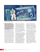
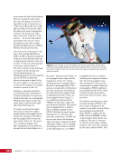
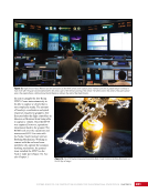
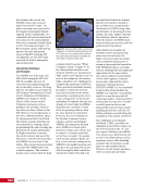
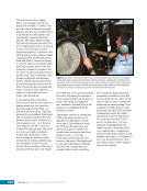
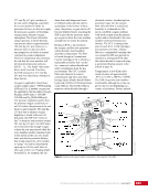
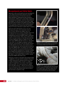
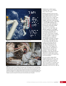
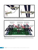
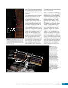
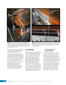
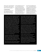
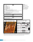
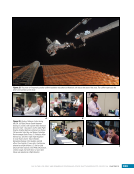
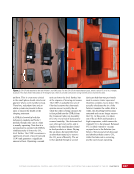
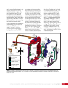
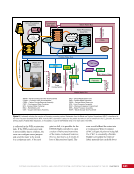
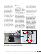
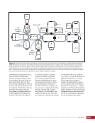
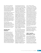
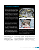
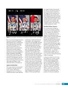
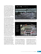
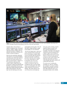
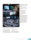
103 SYSTEMS: COMMAND AND DATA HANDLING—THE BRAINS OF THE INTERNATIONAL SPACE STATION CHAPTER 5 The home page Graphical User Interface (GUI) is shown in Figures 4 and 5. At a high level, the home page is a graphical representation of the ISS. Crew members can examine the status of all the systems in a specific module by clicking on the appropriate icon. Alternatively, the crew can examine all aspects of a particular subsystem by selecting the icons for that system along the right side of the screen. Since the ISS is occupied by people from many different cultures, generic icons (e.g., a lightning bolt for the electrical system) are used as much as possible. The GUI graphics are integrated into the station’s Caution and Warning (C&W) system. For example, a module is highlighted red or yellow if a subsystem in that module is experiencing an alarm. Some emergencies, such as fire or toxic atmosphere, can result in the entire crew being isolated in the Russian Segment. A PCS is always maintained in that segment so that insight of the USOS is retained, even if the crew is temporarily cut off. Figure 5. Alarm trace. The crew can use the PCS to zero in on the cause of an alarm. On the home page, a module will turn the color of the alarm class (top left). In this case, the electrical system and environmental systems in Node 3 and the P6 segments indicate an alarm. The crew selects the module that, in the example, shows a caution-level event in the Node 3 Environmental Control and Life Support System (top right). The control page for the rack shows (lower right) that the Carbon Dioxide Removal Assembly is in alarm. Selecting that module brings up a detailed page where the crew and ground can isolate the fault and perform further troubleshooting (bottom left).
Purchased by unknown, nofirst nolast
From: Scampersandbox (scampersandbox.tizrapublisher.com)