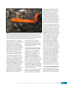
45 SYSTEMS: STRUCTURE AND MECHANISMS—THE INTERNATIONAL SPACE STATION’S SKELETON CHAPTER 3 Freedom design drawings. As many Freedom components were carried into the ISS design with minimal change, the US Segment ISS hatch was the same hatch design as the one originally created for Space Station Freedom. The mounting points for the centerline camera system were not removed from the hatch design in the conversion to the ISS. This meant that when a centerline camera was developed after the Node 1 mission, the hatches already on orbit on Node 1 as well as the hatches on the modules being assembled already had locations in which to mount a centerline camera to the hatch. Thus, the Centerline Berthing Camera System (CBCS)—a cousin to the initial design concept for Space Station Freedom—was rapidly designed, certified, and implemented to assist in berthing pressurized modules to the ISS. The CBM is relatively intolerant to misalignments. When the two halves are 35 cm (14 in.) apart, only 5 degrees of wobble and minimal roll and lateral offsets are allowed (Figure 11). When it comes to misalignments, operators are concerned about both translational and rotational errors. Lateral misalignment is the offset in the up-and-down and side-to-side directions relative to the center of the CBM. Rotational errors are measured in roll (twisting about the center of the CBM) and wobble (a combination of pitch-and-yaw errors). By using the CBCS camera, robotics operators who are looking at a target on the hatch of the new module coupled with a data overlay on the robotics monitor (Figure 12) can detect any misalignments and adjust the position of the module until all misalignments are within limits. The operators can also determine the proximity of the module (the target gets bigger as it gets closer to the camera) and whether it is about to push one of the RTL indicators. CBCS was first used on the STS-98/ISS-5A mission in 2000 the camera was mounted on Node 1 and used to connect the US Laboratory to Node 1. CBCS has been used successfully on every pressurized module installation since that time. Figure 12. The view of an incoming module that an astronaut sees on his or her Robotic Workstation monitor from the CBCS camera. Green reference and targeting lines are computer generated by the robotics system and drawn on top of the video image. These lines assist the crew in aligning the new module. The four quadrants of red lights are reflections of light-emitting diodes around the CBCS camera that are used to illuminate the CBCS target on the incoming element. The camera is looking at the hatch window of the incoming module (Node 2 in this case) and the reflective CBCS target mounted around the hatch window (red chevrons). Unfortunately, a CBCS type of system could not be designed swiftly enough to assist in the connection of the ISS truss segments. Instead, those operations relied on the less- user-friendly SVS along with the on-the-scene direction from nearby spacewalking astronauts. With these astronauts in close proximity to the massive truss segments helping guide the installation, special care and choreography was required to ensure the crew was always safely away from the truss connection points and moving hardware. An External Berthing Camera System (EBCS) was, however, installed on the S3 and P3 trusses. This system is used to assist in installing the cargo carriers to the PAS and UCCAS sites. The targets for this system are installed on the S3 and P3 trusses, and the cameras are installed on the cargo carriers. This is the opposite of the CBCS where the camera is attached to the ISS, and the target is on the new/ upcoming hardware. The cameras on the carriers receive their power from the space station’s robotic arm
Purchased by unknown, nofirst nolast
From: Scampersandbox (scampersandbox.tizrapublisher.com)


