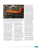
CHAPTER 5 SYSTEMS: COMMAND AND DATA HANDLING—THE BRAINS OF THE INTERNATIONAL SPACE STATION 94 Tier 3 Multiplexer/DeMultiplexers (MDMs). Sensors include devices that can measure the carbon dioxide or oxygen level of the crew’s atmosphere, the pressure inside a cooling loop, the speed of a fan, or the temperature of something. These devices are wired to an Input/Output (I/O) card in the computer. The value read by the sensor is transmitted to the card, which the computer will output to the Tier 2 MDM above it, where it is passed to the Command & Control (C&C) MDM for downlink to the ground. End effectors are items with moving parts, such as a switch or a motor, to effect a change. Some end effectors actually fire pyrotechnics (i.e., explosives) such as those used to release straps holding collapsed radiators in place for launch. Solenoid Driver Output Cards provide the interface between the MDM and the end effectors. When power is applied to the card, a solenoid will physically move to push or pull an item such as a valve into position. The ISS has thousands of these sensors and effectors, and almost all are replaceable on orbit if a repair is required. The Remote Power Control Modules (RPCMs), which are effectively circuit breakers that can be opened or closed via computer, are the most common type of effectors. MCC Telemetry Format Loads (TFLs) Data Dumps File Transfers File Transfers File Transfers File Transfers Commands Commands Data Loads Data Collection Data Distribution Commanding Display Data Legend: PCS Tier 1 MDM Payload MDM Firmware Controller Firmware Controller Sensors Effectors Tier 3 MDM Tier 2 MDM CDC Tier Interfaces Figure 1. Representation of the USOS C&DH system illustrating the tiered nature of the computer system. Tier 1 (the top tier) is the control tier, directing (red lines) all the lower-level computers. Data, or telemetry (purple lines), rise from the lower tiers back to the top where it is radioed to the ground control team or sent to the crew’s portable computer system. Tier 2 (the local tier) is where major functions such as guidance or thermal control are performed. All the sensors, fans, pumps, valves, etc. are controlled at Tier 3 (the user tier). Robustness at the user tier level (Tier 3) is achieved through redundancy of the systems. For example, a critical system may have two independent power feeds so that no interruption of electricity occurs if one power feed fails. Another example is where two separate heaters exist when only one would ever be needed. Tier 3 computers do not have backup MDMs since the systems themselves have layers of redundancy to protect against critical failures of course, spare boxes are available on orbit to replace failed boxes. A summary of all the tier computers is provided in Table 1.
Purchased by unknown, nofirst nolast
From: Scampersandbox (scampersandbox.tizrapublisher.com)


