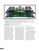
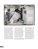
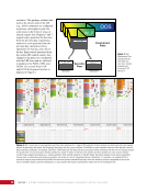
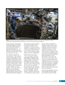
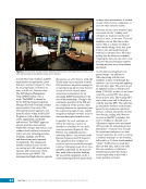
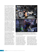
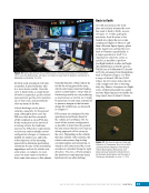
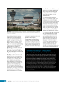
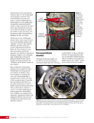
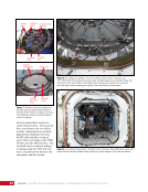
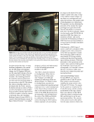
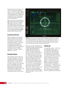
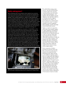
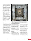
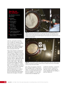
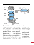
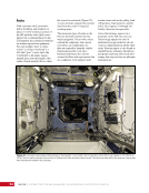
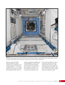
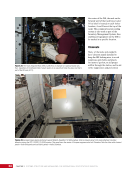
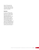
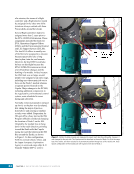
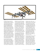
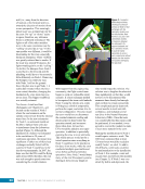
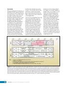
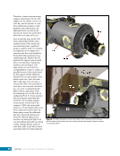
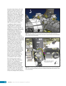
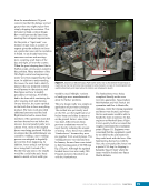
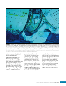
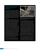
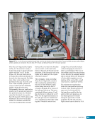
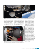
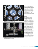
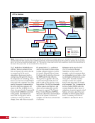
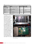
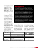
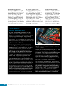
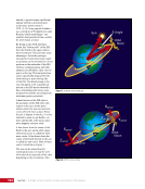
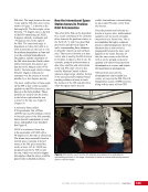
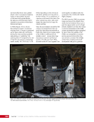
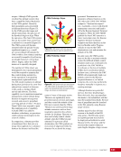
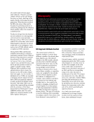
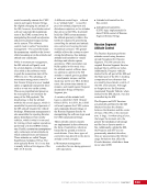
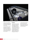
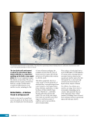
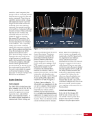
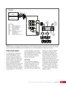
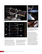
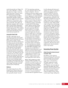
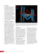
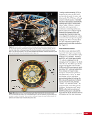
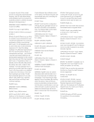
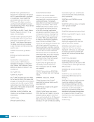
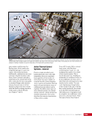
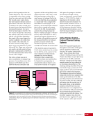
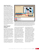
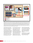
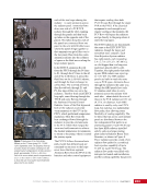
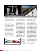
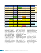
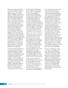
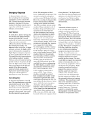
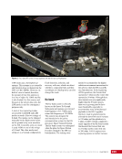
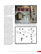
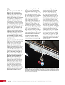
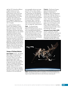
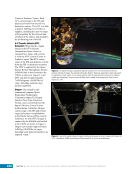
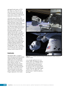
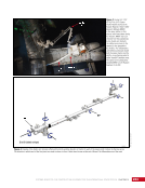
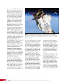
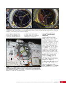
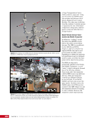
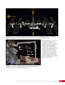
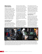
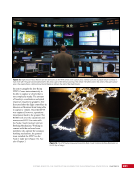
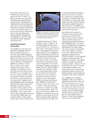
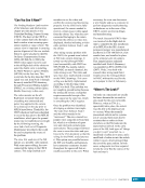
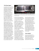
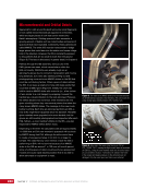
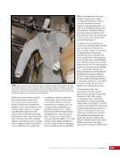
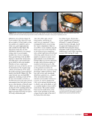
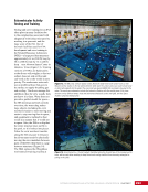
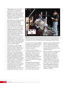
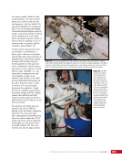
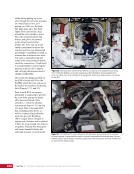
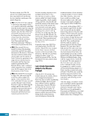
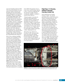
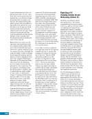
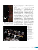
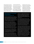
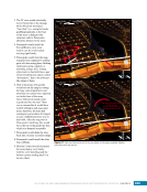
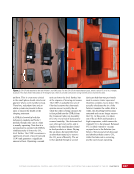
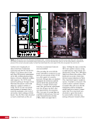
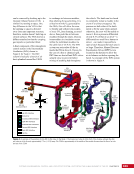
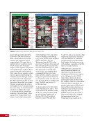
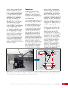
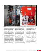
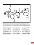
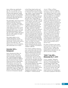
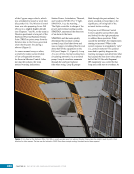
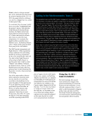
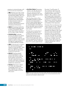
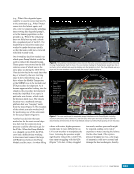
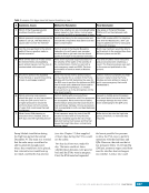
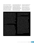
169 SYSTEMS: ELECTRICAL POWER SYSTEM—THE POWER BEHIND IT ALL CHAPTER 9 UTA Inboard Ring Outboard Ring Figure 9. Photo of a SARJ. The SARJ consists of two rings, with a utility transfer assembly (UTA) on the axel and two drive/lock assemblies (not shown). The rings consist of teeth (see Chapter 18) that move like a bike chain on the gear sprocket. The drive/lock assembly is used to either turn the gear teeth or lock the ring in position. The UTA allows commands and telemetry as well as electricity to pass back and forth using a roller ball assembly, shown in Figure 10. A utility transfer assembly (UTA) is located at the center of each SARJ and provides the path for power and data transfer. The UTA has a roll ring structure, which consists of multiple stationary metal plates surrounded by rotating metal rings. Flexible metal rollers, called “flexures,” between each plate and ring maintain a continuous conducting path to pass electrical power or computer signals between the stationary plate and rotating ring. One plate-roller-ring set is required for each power or data connection that must pass through the rotating joint. These roll rings allow for 360º continuous rotation with seamless power and data conduction. See Figure 10. Photo credit: McDonnel Douglas Image s07-17091 Stationary Plate Connection with Cable Idlers Stationary Plate Flexures Rotating Ring Connection Rotating Ring Cable Passthroughs Figure 10. Example roll ring. The gold stationary plate stays fixed while the outer section rotates. Part of a cable (black) is shown in one of the passthroughs on the inner stationary ring (the rotating ring connector is empty in this photo). Power or data is conducted through the metal flexures between the stationary and rotating rings to transfer electricity or data. Photo: Courtesy of Robert C. Dempsey Beta Gimbal Assemblies The BGAs rotate individual SAWs to provide beta angle array pointing capability (i.e., when the ISS is in the nominal +XVV attitude). Normally, each BGA will rotate approximately ±4º a day to compensate for the changing solar beta angle as the Earth orbits the sun. The BGAs provide the structural load path connecting the SAWs to the ISS truss structure while providing 360° rotational capabilities. They include roll rings for data and power transmission (similar to the SARJ UTA), a motor for SAW positioning, and two redundant anti-rotation latches for locking the BGA in specific positions. Software operates the BGA using multiple “modes.” The autotrack mode—the nominal mode—uses data from the Guidance, Navigation, and Control MDM on the relative positions of the ISS and the sun to calculate the angle that the BGAs should be moved to track the sun. The rate mode uses
Purchased by unknown, nofirst nolast
From: Scampersandbox (scampersandbox.tizrapublisher.com)