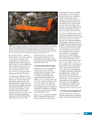
43 SYSTEMS: STRUCTURE AND MECHANISMS—THE INTERNATIONAL SPACE STATION’S SKELETON CHAPTER 3 were flexing and bending at the same time each thruster firing occurred. Each thruster firing then further excited or increased the bending and loads being experienced by the ISS structure. After the reboost, engineers used structural measurement data to assess any damage to the ISS structure (none occurred) and the potential impact to the overall lifetime of the structure (engineers noted a slight, nearly negligible reduction in ISS structural life of some components). A household example might be akin to having an off-balance load in a clothes washer. In this situation, the washer will “jump around” due to the off-balanced load. This will cause some wear and fatigue on the spinning parts and structure of the washer. A single off-balance event will cause minimal impact or damage to the washer. However, if the washer ran with numerous off-balance loads for long periods of time, the hardware would degrade and the washer would likely break or fail earlier than designed or expected. Why is there no S2 or P2 truss? The heritage of the ISS design shows up in many different, oftentimes small, ways. One of the larger but perhaps not as obvious instances is with the naming of the truss segments. Although the ISS does not have an S2 truss or a P2 truss, these truss segments were actually in the Space Station Freedom design (the precursor design to the ISS). These truss segments were going to house the thrusters needed to control the attitude and altitude of Freedom. When the Russian Space Agency became an ISS Partner and its modules took the role of housing the thrusters, the S2 and P2 truss elements were no longer needed and were removed from the design. The overall design was far enough along in development that it was decided to not rename the other truss segments. Truss Attachment Sites Another component of the two truss attachment mechanisms is a capture latch. This component was used in a fashion similar to the latches on the CBM. When a new piece of truss was close enough (i.e., RTL) to the ISS truss, the latch would be used to grab a capture bar on the new truss and draw it closer to the ISS truss. This capture latch can best be pictured as a large claw that would close around that capture bar. Due to its robust and adaptable function, this capture latch/claw design is used in many other places externally on the ISS. As mentioned previously, a number of science experiments are mounted on the ISS truss. Also, a large number of spare parts are mounted on the truss for use by spacewalkers or the Special Purpose Dexterous Manipulator robot to fix broken external hardware (see Chapter 15). Spare parts and many research experiments are attached to large carrier platforms, either External Stowage Platforms or Expedite the PRocessing of Experiment to the Space Station (ExPRESS) Logistics Carriers. These carriers are secured to the truss using a Payload Attachment System (PAS) or an Unpressurized Cargo Common Attachment System (UCCAS). These systems use mechanisms that implement the common capture latch design as well as Umbilical Mating Assemblies (UMAs). The UMAs provide power and data from the ISS to the carrier. Two UCCAS sites are located on the P3 truss, and four PAS sites are located on the S3 truss. Reference Figure 4 in the Introduction to identify the hardware carriers attached to the S3 and P3 trusses on the ISS. In that figure, the Alpha Magnetic Spectrometer telescope is mounted to one of the S3 PAS sites. As has been pointed out, the attachment mechanisms of the ISS are required to hold a large amount of mass and withstand significant loading, bending, and vibration. The mechanisms themselves must be very robust and capable to ensure the various designs will perform these functions. Care had to be taken during assembly operations using these mechanisms to make certain that the mechanisms, while actuating latches or bolts, were operated in a specific sequence. This sequence was analyzed prior to the operation to ensure the use, or a failure of a component during that use, would not cause damage to any of the ISS hardware involved (including the robotic arm). This is just one more example where the operations and engineering teams worked closely together to ensure the method of operations planned by the operations teams would stay within the limits analyzed by the engineering teams (often integrated by the End-to- End Berthing Integration Team).
Purchased by unknown, nofirst nolast
From: Scampersandbox (scampersandbox.tizrapublisher.com)


