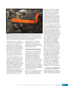
CHAPTER 11 SYSTEMS: THERMAL CONTROL—THE “CIRCULATORY SYSTEM” OF THE INTERNATIONAL SPACE STATION 200 S1 or P1 Truss Habitable Modules S0 Truss Accumulator Flow Control Valve Pump Nitrogen Tank Assembly Ammonia Tank Assembly Pump Module Radiators Cooled Ammonia Warmed Ammonia Ammonia Supply Nitrogen On-orbit Replaceable Unit Location on ISS Interface Heat Exchangers Electrical System Hardware Thermal Radiator Rotator Joint Nitrogen Tank Ammonia Tanks NH3 NH3 N2 Figure 6. A simplified schematic showing the major components and flow paths of the External Thermal Control System (ETCS). The ETCS is very similar to the PhotoVoltaic Thermal Control System shown in Figure 5. Starting in the pump module, a pump (green) pushes cool ammonia (blue) to either the electrical distribution systems on the exterior of the ISS or heat exchangers on the habitable modules where heat is picked up from the Internal Thermal Control System (discussed below and shown in Figure 10). The warm ammonia (red) passes through a rotating mechanism called the Thermal Radiator Rotator Joint to radiators where the heat is transmitted to space. The cooled ammonia (blue) returns to the pump module to repeat the cycle. A flow control valve in the pump module allows mixing of warm and cool fluid to adjust the temperature of the loop. An Ammonia Tank Assembly (ATA) performs the role of an accumulator, maintaining the pressure on the fluid line as the liquid expands or contracts through the orbit or year. Unlike the PVTCS, the ETCS has a replenishable nitrogen tank to maintain pressure at the ATA. A fixed-pressure accumulator in the pump module is too small to maintain loop pressures year round, but can maintain stable pressure for short periods if the ATA/NTA combination is unavailable. The ETCS pump is located within an assembly called the pump module, which consists of a Pump and Control Valve Package, an accumulator, several valves, and a suite of sensors to monitor temperature, pressure, flow rate, and ammonia quantity (Figure 6). The pump and control valve package contains a pump, an FCV, sensors to monitor temperature and flow rate, and a firmware controller to control the pump and FCV. Each ETCS loop has one pump module, located in the S1 truss segment for Loop A and the P1 truss segment for Loop B. In August 2010 and December 2013, the pump module on Loop A failed, cutting off half the cooling and leaving the station one failure away (on Loop B) from losing all cooling. Without cooling, the equipment would overheat and ultimately fail. Since most of the critical systems have two identical instances to provide for redundancy, the failure of one loop meant half of these systems had to be shut down. If the other loop failed, or if any of the redundant equipment that it cooled broke, the station would no longer be viable for supporting the crew. The crew conducted three emergency spacewalks later that month to restore functionality (See Chapter 20). As with the PVTCS, the accumulator in the pump module accommodates thermal expansion and contraction of ammonia within the pump
Purchased by unknown, nofirst nolast
From: Scampersandbox (scampersandbox.tizrapublisher.com)


