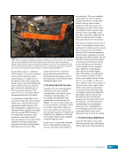
57 SYSTEMS: STRUCTURE AND MECHANISMS—THE INTERNATIONAL SPACE STATION’S SKELETON CHAPTER 3 Figure 25. An example of an avionics rack. This is the Moderate Temperature Thermal Control System rack (see Chapter 11) in the US Laboratory with its closeout panels removed, prior to it being installed at the LAB1S6 location. On the left side of this rack is a fluid pump that is covered by black insulation. On the right half of this rack is a heat exchanger (top half) and cabin fan (bottom half) that, together, make up one of the Laboratory’s air-conditioning systems. Figure 26. A payload rack, Expedite the Processing of Experiments to the Space Station (ExPRESS) 4, in the US Laboratory module during Expedition 4 (2002) prior to it being relocated to the JEM. An ExPRESS rack has a number of locker locations where smaller payloads can be installed these payloads can get power and data from the central area of the rack. The smaller locker payloads can be exchanged regularly, and can even be returned to the ground, if necessary. Figure 27. The Waste and Hygiene Compartment (WHC), located at NOD3F4, is an example of a rack designed for crew support. The WHC is the bathroom for the US Segment. To use this facility, crew members close a privacy curtain (located approximately where the camera was located to take this photo). Liquid waste enters a funnel at the end of the hose, as seen in the upper-right corner of the above image. Solid waste goes into the solid waste receptable (metal can), as seen in the middle of the image. Liquids and solids are drawn into their respective destinations by airflow from a fan that runs when the WHC is powered on.
Purchased by unknown, nofirst nolast
From: Scampersandbox (scampersandbox.tizrapublisher.com)


