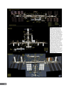
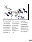
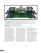
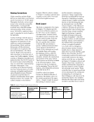
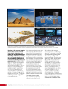
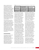
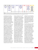
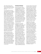
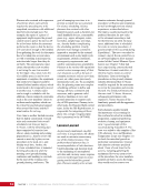
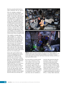
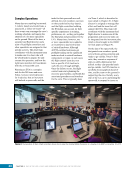
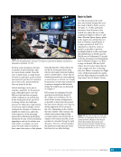
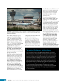
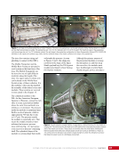
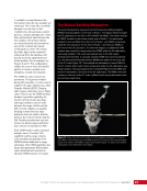
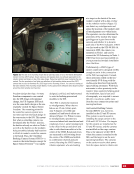
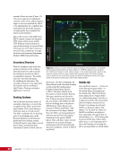
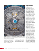
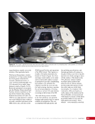
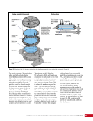
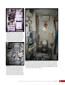
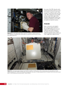
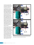
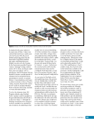
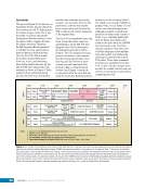
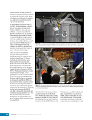
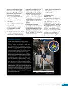
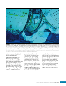
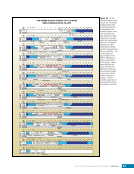
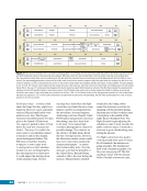
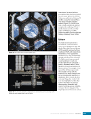
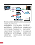
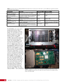
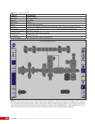
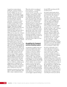
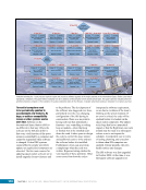
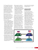
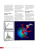
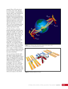
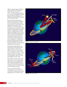
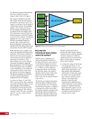
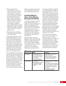
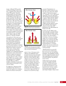
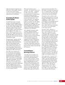
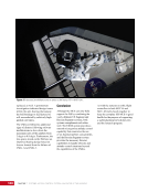
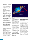
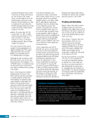
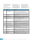
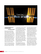
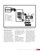
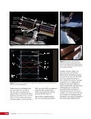
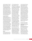
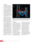
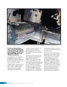
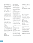
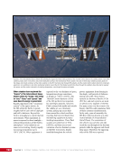
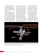
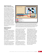
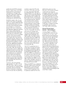
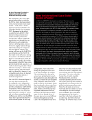
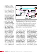
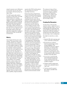
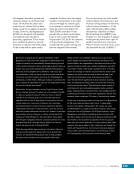
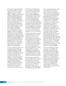
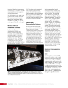
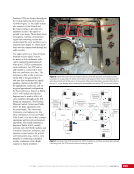
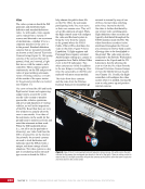
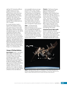
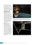
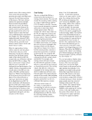
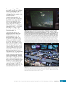
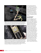
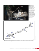
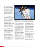
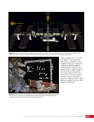
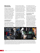
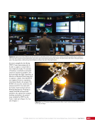
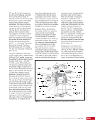
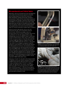
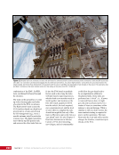
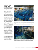
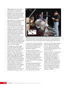
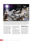
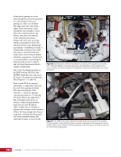
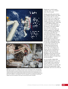
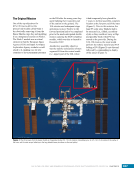
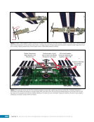
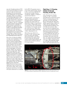
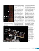
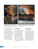
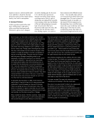
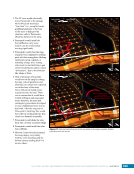
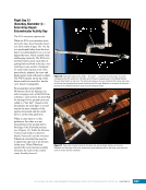
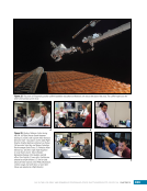
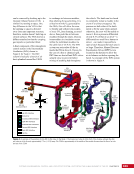
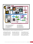
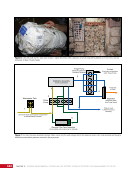
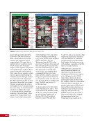
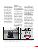
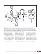
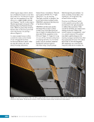
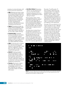
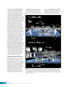
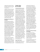
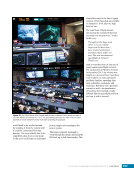
CHAPTER 18 DAY IN THE LIFE: RISKY AND REWARDING SPACEWALKS—SPACE SHUTTLE MISSION STS-120/ISS-10A 308 Folded Blanket Boxes Mast Canister Figure 2. Graphic of the installation of the P6 module onto P5 during STS-120/ISS-10A. The solar arrays are folded up, accordion-style, in the long blanket boxes that are protruding from the cylindrical mast canister. Left image shows the P6 being maneuvered into position, whereas the right image shows it just prior to mating. Graphic generated using Johnson Space Center’s Virtual Reality Laboratory software. Mobile Transporter, Base System, and Robotic Arm. Furthest point to port side to which the Mobile Transporter can travel. P6 in final location. These two blankets are together called “4B.” These two blankets are together called “2B.” Figure 3. The huge solar arrays give the ISS an impressive wingspan, as seen here overlaid on an American football field. The Mobile Transporter is constrained to the middle truss sections by the large rotating Solar Array Alpha Joints. After the P6 truss module relocation to the far-port end of the ISS, the arrays are not accessible by an EVA crew member standing on the robotic arm due to the Mobile Transporter limitations. This lack of reach created a challenging circumstance during the STS-120 mission.
Purchased by unknown, nofirst nolast
From: Scampersandbox (scampersandbox.tizrapublisher.com)