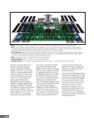
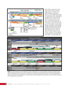
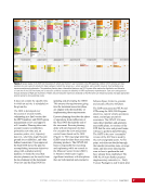
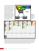
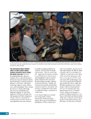
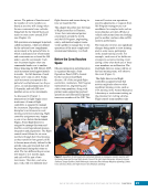
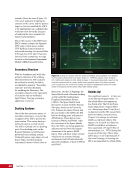
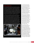
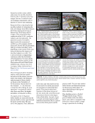
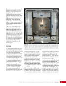
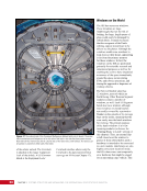
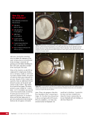
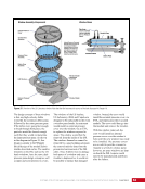
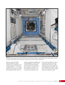
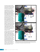
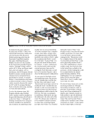
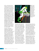
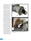
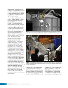
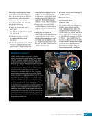
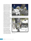
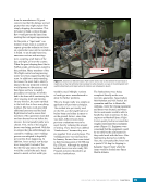
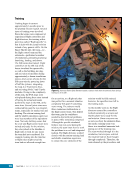
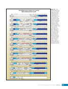
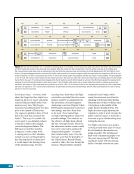
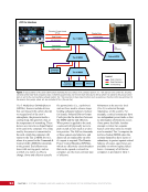
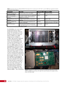
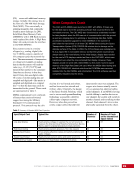
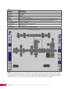
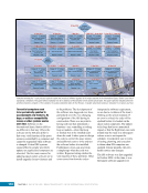
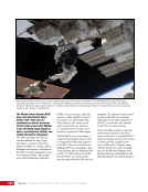
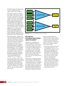
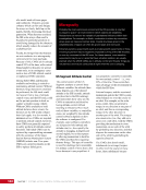
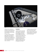
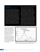
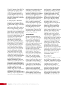
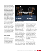
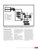
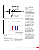
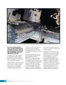
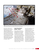
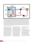
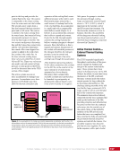
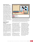
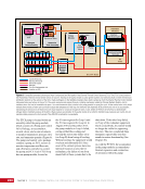
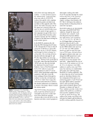
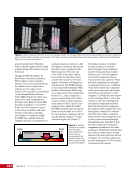
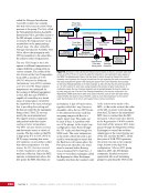
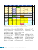
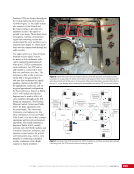
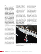
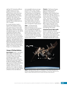
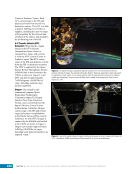
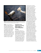
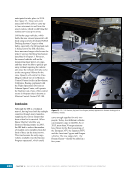
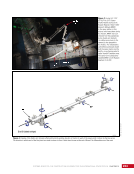
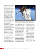
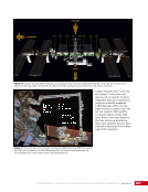
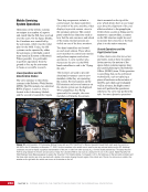
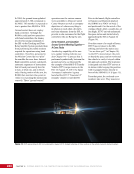
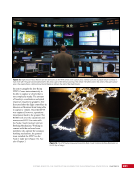
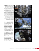
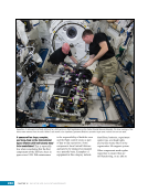
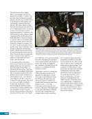
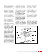
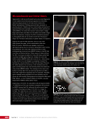
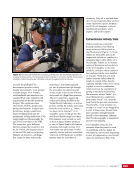
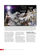
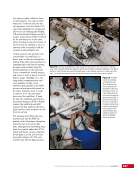
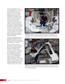
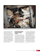
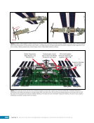
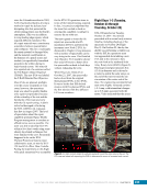
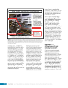
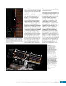
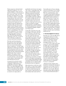
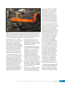
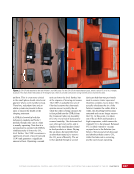
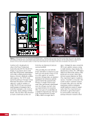
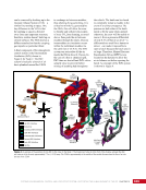
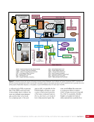
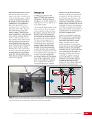
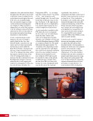
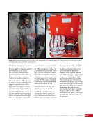
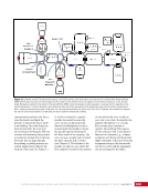
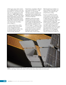
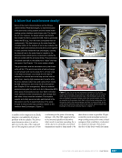
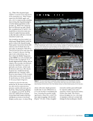
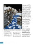
205 SYSTEMS: THERMAL CONTROL—THE “CIRCULATORY SYSTEM” OF THE INTERNATIONAL SPACE STATION CHAPTER 11 Active Thermal Control— Internal Cooling Loops The equipment in the various ISS pressurized modules is cooled by the ITCSs, which function similarly to the external systems. Each major module—LAB, Node 2, Node 3, Japanese Experiment Module, and Columbus Module—has a separate ITCS. Equipment in the airlock is cooled by the LAB ITCS. The internal cooling system in each of these modules performs the same function and has roughly the same design even though there are differences in each module due mainly to differing needs, but also because of slightly different design approaches among the contractors who provided the systems. This section will focus on the LAB ITCS as an illustration of the ISS ITCS, then touch on the differences among the systems in the different modules. Water is used in the loops inside the ISS ammonia is used in the cooling loops external to the ISS. Since water provides high thermal capacity (i.e., it is able to absorb a great deal of heat) with low viscosity (i.e., flows easily without requiring powerful pumps) and is not harmful to humans, it was a straightforward choice for internal cooling systems that operate at moderate temperatures. When the International Space Station Needed a Plumber In 2004, the 2B PVTCS developed a small leak. The leak was slow enough that it was tolerated. However, in 2012, the rate of leakage greatly accelerated and it was possibly increasing exponentially fast. At that rate, the loop would exhaust its ammonia supply fairly quickly. Fortunately, a spare, dormant system—the EETCS—was available. The operations team quickly developed a contingency spacewalk to replumb the ammonia flow from 2B through the TTCR of the EETCS. This was accomplished during an extravehicular activity (EVA) when the crew put in two fluid line hoses to connect the two systems. The TTCR had been retracted after it had been decommissioned, so it also had to be redeployed manually by the spacewalking astronauts. Although this did not stop the leak, it did show that the leak was not due to a hole in any of the myriad little tubes inside the radiator panel, which would be extremely hard to repair, if at all. In May 2013, the rate had again increased when ISS Commander Chris Hadfield noticed ice flakes coming from the port truss while performing an EVA. At the new rate, the loop would potentially be unable to sustain cooling in 24 to 48 hours. Once again, the operations team quickly put together a spacewalk within 48 hours to replace the pump assembly, which ultimately fixed the leaking system. In November 2015, the jumpers were removed and the cooling system returned to its nominal configuration. In a follow-on EVA in August 2016, the TTCR was retracted again and returned to a dormant storage configuration until it may be needed in the future. The LAB ITCS, shown in Figure 10, is a water loop system that can be configured as two independent loops or as one combined loop, thus providing redundancy and flexibility in operations. When configured as two separate loops, each loop has a pump assembly, a number of valves, and water lines passing through the LAB pressure shell to reach the IFHX where heat is passed from the ITCS to the external system. In each loop configuration, warm water flows through the pump and is then sent to the heat exchangers for cooling. The cooled water flow then splits across many parallel paths to reach the equipment in racks throughout the module, is warmed by that equipment using coldplates, and returns to the pump to start the circuit again. Along that circular path, valves control how much water flows through different paths, thereby controlling loop and equipment temperatures and loop pressures. The ITCS has only three types of valves, though valves of the same type serve several different functions throughout each loop. Each of the independent loops has a three-way valve that moderates flow between the racks of equipment that need cooling, and a line that bypasses those racks. This valve, called the System Flow Control Assembly Modulation Valve, provides a constant differential pressure across the system. Each loop also contains a pump shutoff valve that provides the ability to isolate a pump from water flow when the pump is not in use. Each loop also has a three-way valve controlling the water flow through a heat exchanger, thus controlling the temperature of the loop (i.e., more flow to the heat exchanger for a colder loop, less flow to the heat exchanger for a warmer loop). A unit
Purchased by unknown, nofirst nolast
From: Scampersandbox (scampersandbox.tizrapublisher.com)