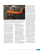
CHAPTER 3 SYSTEMS: STRUCTURE AND MECHANISMS—THE INTERNATIONAL SPACE STATION’S SKELETON 46 instead of from the truss (Figure 13). This novel approach of putting the cameras on the carrier and the passive target on the truss enabled the EBCS to be implemented on a schedule that would not slow down the fast pace of readying the truss segments for launch and installation. Figure 13. A photo of a monitor of the ISS robotics workstation during installation of an Expedite the Processing of Experiments to the Space Station (i.e., ExPRESS) Logistics Carrier during the STS-129/ISS-ULF3 mission in 2009. Similar to Figure 12, the monitor shows both a view from the centerline camera as well as a green, digitally drawn graphical overlay. The robotics operators (crew or ground) use the overlay lines to gauge the amount of misalignment between the target (center of the picture) and the camera (ring of light-emitting diodes). Due to the success of the CBCS and EBCS camera systems, the Japanese HTV cargo vehicle uses a similar HTV Berthing Camera System to assist with inserting its Exposed Pallet (EP) back into HTV after it has been removed from a temporary stowage location on the Japanese Experiment Module (JEM) Exposed Facility. Secondary Structure With the foundation and walls (the primary structure) of the orbiting laboratory built, the ISS needed to be outfitted to actually be able to accomplish its mission. “Secondary structure” provides the means for outfitting the laboratory. The secondary structure is the equivalent of elements such as wallboard, light fixtures, flooring, and major appliances in a home. Docking Systems One of the first necessary pieces of secondary structure is a way for the occupants of the ISS to get into the space station. This means having a method to dock a crewed vehicle. The ISS is outfitted with six docking ports. Four docking ports on the Russian Segment use the Russian probe-and-cone docking system. Visiting Progress cargo ships, crewed Soyuz ships, and the European Automated Transfer Vehicle dock to these ports. On the US Segment, the Space Shuttle used a Russian docking system called the Androgynous Peripheral Attachment System (APAS). The Space Shuttle used this system to dock with the Russian Mir space station as well as to the ISS. Whereas the Space Shuttle had the active half of the APAS, the ISS had two docking ports with passive APAS halves. These halves were located on PMA2 and PMA3. After the retirement of the Space Shuttle fleet, the PMAs are being updated to add International Docking Adapter extensions to the passive APAS halves. This will allow future crewed vehicles to use a newer docking mechanism, built off internationally agreed-to standards, to dock to PMA2 and PMA3. Shields Up! One significant concern—in fact, one of the ISS Top Program Risks—is the orbital debris environment in low-Earth orbit. The US Air Force tracks large pieces of space debris (i.e., debris larger than 10 cm [4 in.] in diameter) and the ISS can perform debris-avoidance maneuvers (see Chapter 8) to change its orbit and thereby avoid those objects. The impact of a 10 cm (4 in.) object on the ISS would have an explosive force equivalent of 7 kg (15 lbs) of trinitrotoluene (i.e., TNT). Being able to get out of the way of these large debris pieces is an important part of the overall strategy of ensuring the ISS is not penetrated by orbital debris.
Purchased by unknown, nofirst nolast
From: Scampersandbox (scampersandbox.tizrapublisher.com)


