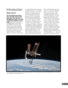
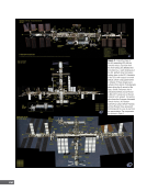
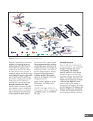
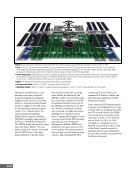
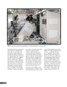
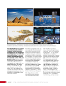
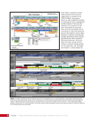
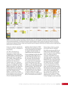
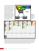
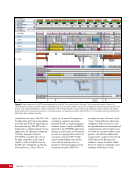
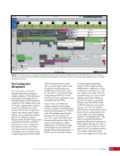
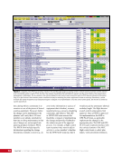
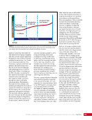
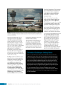
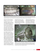
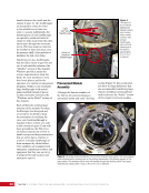
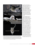
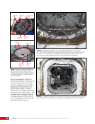
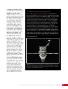
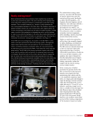
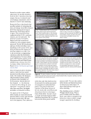
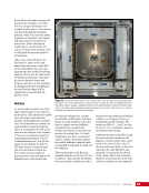
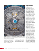
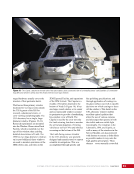
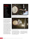
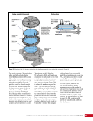
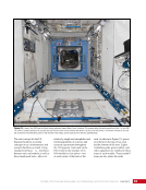
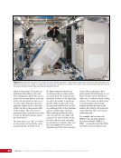
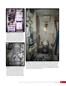
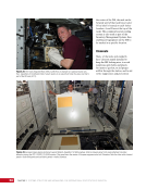
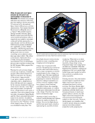
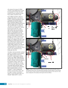
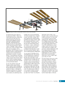
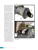
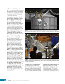
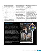
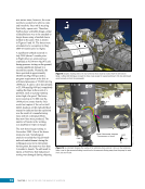
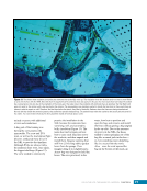
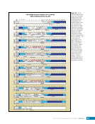
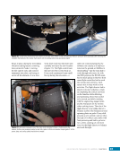
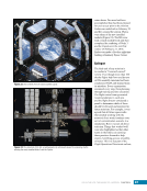
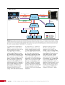
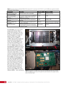
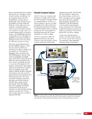
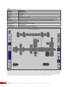
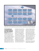
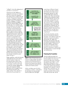
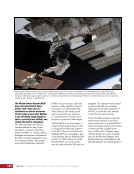
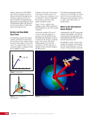
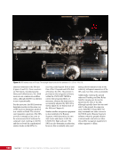
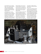
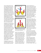
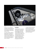
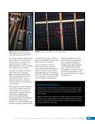
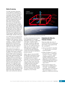
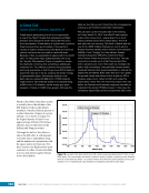
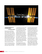
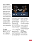
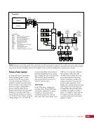
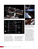
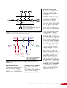
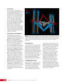
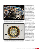
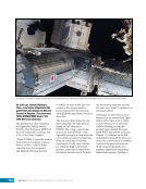
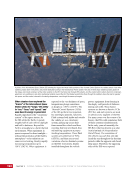
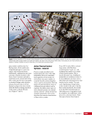
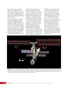
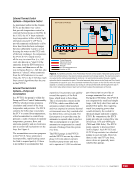
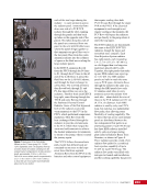
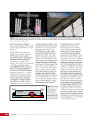
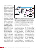
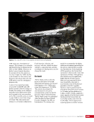
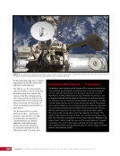
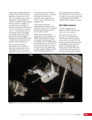
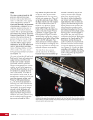
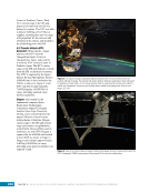
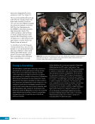
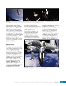
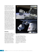
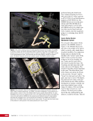
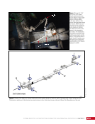
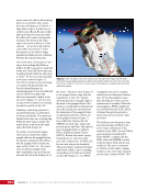
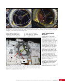
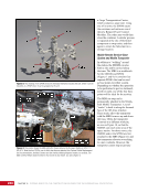
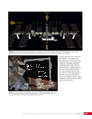
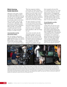
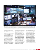
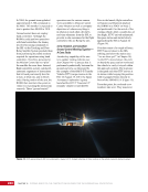
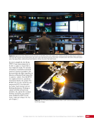
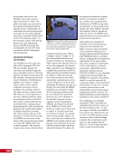
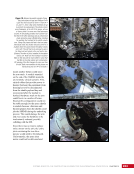
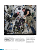
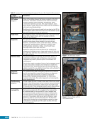
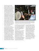
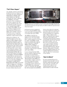
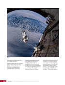
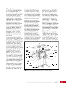
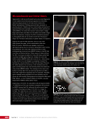
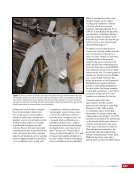
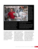
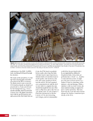
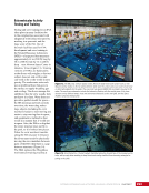
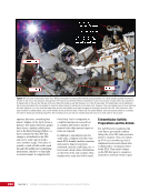
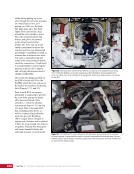
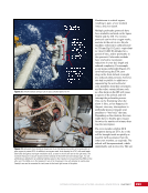
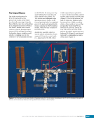
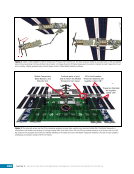
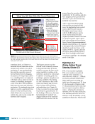
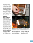
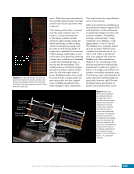
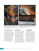
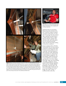
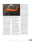
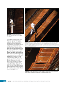
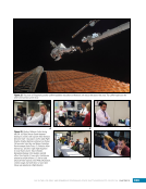
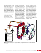
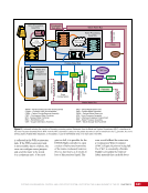
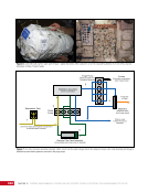
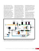
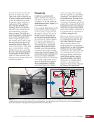
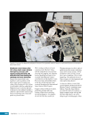
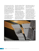
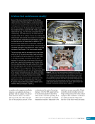
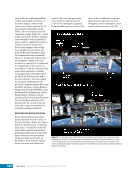
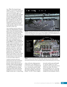
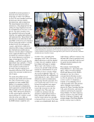
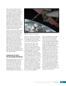
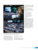
CHAPTER 3 SYSTEMS: STRUCTURE AND MECHANISMS—THE INTERNATIONAL SPACE STATION’S SKELETON 42 Truss Assembly The ISS is not solely a collection of connected cylindrical modules in which the crew can live and work. In addition to these modules, the ISS needs the additional truss structure to support its eight solar arrays, its external radiators, the equipment to run all of those external systems, and a place to mount the large number of science experiments that are running in the space vacuum. This truss system, often called the “backbone of the ISS,” is attached to the US Laboratory module by 10 struts that connect to the center S0 truss segment. The truss was, of course, not flown up as a single unit. Rather, smaller truss segments were flown up, and the truss was assembled on orbit. As can be seen in the image of the ISS in Figure 1, one side of the truss system appears to be a mirror image of the other side—and that is indeed the case. Not only are the truss segments mirror images, the system hardware installed on the truss is mirrored in many places. For example, for the Port Solar Alpha Rotary Joint, which connects the P3 and P4 trusses (see also Figure 3 in the Introduction and Figure 8 in Chapter 9), to turn in the same direction as the Starboard rotary joint, ground controllers must use commands with values that are the negative of what is sent to the Starboard joint. If this inverse-value commanding were not performed, the two joints would turn in opposite directions because the joints are on opposite sides of the truss but use the same rotary joint control software. Assembly of some of the truss segments was completed using only robotic arms and computer commands. The computer-controlled attachment mechanism, known as the Segment-to-Segment Attachment System, connects S0 to S1, S1 to S3, S0 to P1, and P1 to P3. During EVAs, astronauts used handheld power tools to drive the interfacing bolts of the Rocketdyne Truss Attachment System for other truss segment connections, namely the Z1 to P6 (during the early ISS assembly time frame), S4 to S5, S5 to S6, P4 to P5, and P5 to P6 connections (all the connections outboard of the P3/S3 trusses). The mechanical concept was the same whether an automated mechanism or a manual mechanism was used—four large bolts on one side of the truss segment were driven securely into the receiving nuts of the adjoining truss segment. All of the major truss pieces, all of the large components attached to the trusses (some of which rotate), and all of the hardware within the truss segments are connected through only four bolts/nuts at each truss element interface. This entire truss, which is 109 m (375.5 ft) in length, is connected to the US Laboratory module by 10 attachment struts. Structural Health A primary engineering concern is how loading events can cause the hardware of the ISS to fatigue over time, which may impact how long the engineering teams believe the spacecraft structure can remain in orbit without failing. With the significant mass of the ISS and the loads it experiences being handled across the relatively few connecting points of the truss, engineering teams need to ensure their ground models of the ISS structural stress and loading match what is actually being experienced by the vehicle. A few of the various loads that the truss must withstand include vibrations from rotating equipment, crews pushing off interior walls, contact with a vehicle that is docking, and thermal expansion and contraction. The ground model comparison is especially important in the assessment on whether the lifetime of the ISS hardware can be certified beyond the original design life expectancy. A number of instrumentation systems have been installed both inside the ISS pressurized modules and externally on the ISS truss. These systems—the Internal Wireless Instrumentation System, the External Wireless Instrumentation System, and the Structural Dynamics Measurement System, along with others—collect engineering data on the stress, strain, dynamics, and accelerations imparted on the ISS structure during various events and stages of ISS assembly and operations. These data are not only useful for improving the accuracy of ground engineering models to help perform analysis for future events such as upcoming vehicle dockings or space station maneuvers, the data are also useful for reconstructing what impact past events may have had on the ISS structure. For example, in 2009, a misconfiguration of some thruster parameters during a reboost caused the Service Module main engines to pulse at a frequency that was a harmonic with the ISS truss. This essentially meant that the ISS truss, along with the attached ISS modules,
Purchased by unknown, nofirst nolast
From: Scampersandbox (scampersandbox.tizrapublisher.com)