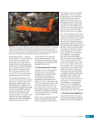
37 SYSTEMS: STRUCTURE AND MECHANISMS—THE INTERNATIONAL SPACE STATION’S SKELETON CHAPTER 3 The truss also contains wiring and plumbing to connect all the ORUs. The Mobile Transporter and the Mobile Base System are mounted to a rail system on the front face of the truss. The Mobile Transporter can be moved to one of eight different worksites along the length of the truss. The space station’s robotic arm can be based on the Mobile Base System at any of these worksites. It is this mobility of the arm that enabled the assembly of the station’s truss and modules. These systems are covered in more detail in the Chapter 15. The cylindrical modules of the ISS—be they American, European, Japanese, or Russian—connect to each other to create a pressurized habitat where the crew lives and works in a shirtsleeve environment. The pressure inside the modules is maintained near Earth’s sea-level pressure, which is approximately 760 mm Hg (1 atm or 14.7 psi). The pressure outside the modules is essentially zero. That means the module structures must withstand an immense pressure force (760 mm Hg / 14.7 psi) across every facet of its pressure-containing shell. The cylindrical shape of the modules is a strong shape that readily withstands this pressure. As seen in Figures 2 and 3, this shape also conforms to the shape of the Space Shuttle payload bay (for US Segment modules) and launch vehicle fairings (for Russian modules). Node 3 Cupola Figure 2. Left image is the empty payload bay of orbiter Endeavour. The front of the payload bay is to the right where the Orbiter Docking System is installed and two flight deck windows are visible. The payload bay was 4.6 m (15 ft) in diameter and 18 m (60 ft) in length. This meant any cargo in the payload bay could be no larger than a 4.6 m (15 ft) diameter cylinder. The right image is the payload bay configuration for Space Transportation System (STS)-130/ISS-20A with Node 3 and Cupola as the primary cargo. Notice how the cylindrical shape of the module conforms to the shape of the payload bay. Figure 3. The US Laboratory module, Destiny, is supported by a frame that allows it to be rotated as it is being built. The reinforcing ribs that make up a waffle pattern that crisscrosses the primary pressure shell of the module can be seen. These pieces are normally under the orbital debris shielding and thermal insulation that makes each module appear smooth and round (as with Node 3 in Figure 2). This reinforcement is what gives each module enough strength to contain the atmospheric pressure that allows the crews to work in a shirtsleeve environment. Although the primary purpose of the pressurized modules is to keep the atmosphere in, and thus keep the crew alive, the modules must have feedthroughs to allow fluids (liquid and gas), power, and data to
Purchased by unknown, nofirst nolast
From: Scampersandbox (scampersandbox.tizrapublisher.com)


