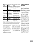
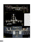
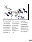
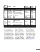
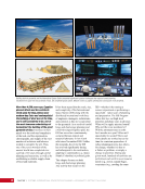
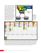
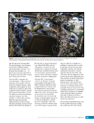
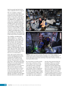
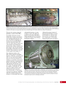
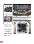
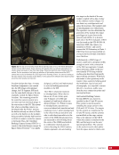
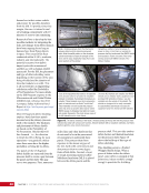
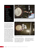
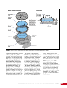
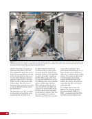
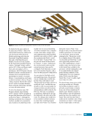
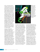
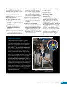
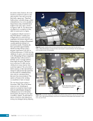
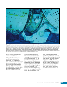
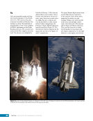
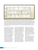
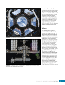
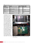
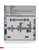
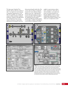
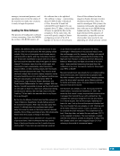
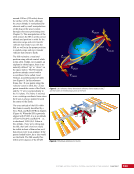
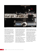
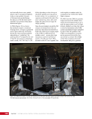
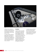
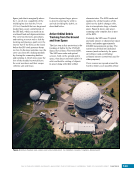
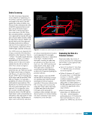
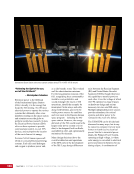
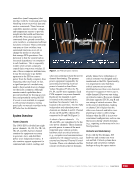
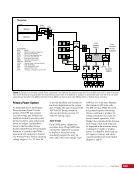
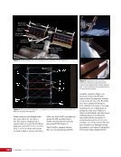
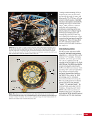
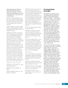
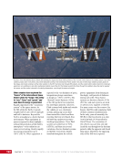
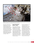
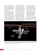
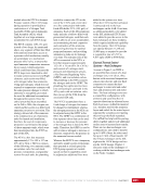
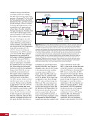
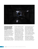
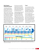
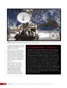
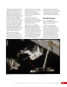
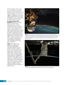
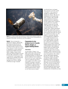
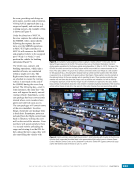
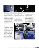
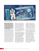
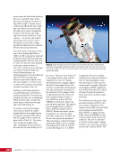
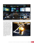
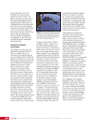
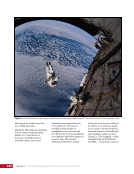
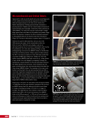
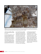
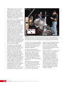
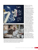
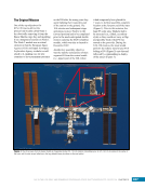
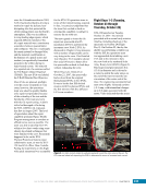
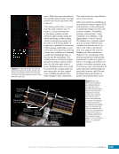
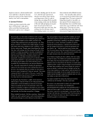
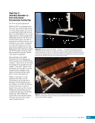
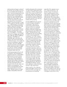
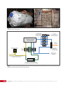
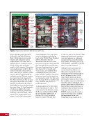
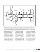
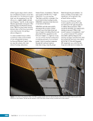
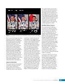
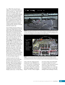
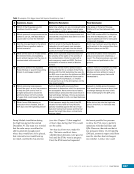
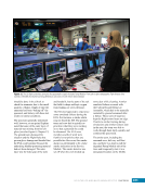
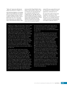
CHAPTER 11 SYSTEMS: THERMAL CONTROL—THE “CIRCULATORY SYSTEM” OF THE INTERNATIONAL SPACE STATION 198 arrays and two pairs of ammonia loops, thus providing power and cooling to the evolving space station much earlier than originally designed. This was done to expedite human presence on the ISS and begin the ISS research program. The P6 truss segment was outfitted with two cooling loops to provide cooling to the habitable modules, specifically to support the ITCS and allow for early activation of interior systems. The augmented P6 truss was installed on the zenith face of the ISS during STS-97/ISS-4A in late 2000, during the third ISS assembly flight of the Space Shuttle. The additional cooling loops were known as the Early External TCS (EETCS). Along with the 2B and 4B solar arrays and associated power channels, the EETCS allowed for a complete activation of the Laboratory Module (LAB) systems once the LAB was installed on STS-98/ISS-5A in 2001. See Figure 4. The P6 truss stayed in this location while the remainder of the ISS was built around it. The early external cooling system was deactivated with the arrival of the remaining truss segments in 2006 and 2007 and the activation of the permanent ETCS. Ultimately, the P6 truss was relocated to its design location as an outboard truss segment, though not without incident (see Chapter 18). Power channels 2B and 4B and their associated cooling loops are again active however, the EETCS is permanently retired, and provides spare parts for eight of the cooling loops on the ISS. The permanent system shares many common features with the EETCS, which would later play yet another role, as detailed in this chapter. The final configuration of the ISS includes two types of ETCSs. Loops A and B form a redundant pair of loops that provide cooling for the core of the ISS. Eight smaller ammonia loops, known as the PhotoVoltaic TCS (PVTCS), each service one channel of the electrical system, and are named for the power channel they support (e.g., PVTCS 1B for the 1B power channel). (See also Chapter 9.) Starboard Radiator Trailing Radiator PhotoVoltaic Radiator Figure 4. Picture of the early space station after STS-98/ISS-5A. The P6 module with its set of arrays and the EETCS was temporarily attached to the Z1 truss. Two radiators labeled the trailing EETCS (since it pointed aft) and starboard (since it pointed starboard) provided cooling for the entire US On-orbit Segment. The PhotoVoltaic system on P6 has its own TCS called the PhotoVoltaic TCS with a forward-pointing radiator called simply the “PVR” (PhotoVoltaic Radiator), which provides cooling to electrical power generation and storage systems on the element.
Purchased by unknown, nofirst nolast
From: Scampersandbox (scampersandbox.tizrapublisher.com)