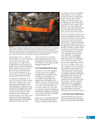
CHAPTER 9 SYSTEMS: ELECTRICAL POWER SYSTEM—THE POWER BEHIND IT ALL 166 conversion. The three types of DDCUs include: external, located on the truss segments internal, located inside pressurized modules and heat pipe units, located on the Z1 truss. Although multiple differences exist, the main distinguishing feature of these converter units are how they are cooled. External DDCUs (cooled by the ETCS loops) and internal DDCUs (cooled by the Internal Thermal Control System) (see Chapter 11) are each designed to output 6.25 kW of power. Heat pipe DDCUs are rated to output only 3 kW of power due to the limited cooling provided by the heat pipes (i.e., small radiators that rely on the release of heat during the phase change of liquid ammonia to gas instead of active pumps). External and heat pipe DDCUs share the same external housing (i.e., thermal insulation and micrometeoroid shielding), which is not required for the internal units. The DDCUs operate on a demand- feed basis, meaning they will try to feed any amount of downstream loads, up to their maximum output trip limits. As the current draw increases (i.e., more loads), the voltage on the output decreases. The converter unit senses this drop and increases its power output to maintain the set point. Similarly, as loads are turned off, the current decreases, thereby increasing the voltage. The DDCU will sense this increase and respond to by decreasing its output. Two DDCUs are configured in a parallel configuration in several locations. In this configuration, each one receives primary power from a different power channel however, the outputs of the two units are merged together to allow up to 12.5 kW to feed downstream loads. As long as the load is not greater than 6.25 kW on a single DDCU, these DDCUs can be configured to balance loads between the two input channels. If one of the parallel convert units were to fail, the other could still support up to 6.25 kW of downstream loads. The DDCUs have multiple safing functions that will automatically deactivate the unit if off-nominal input/output currents, voltages, or temperatures are detected by on- board computers. Power Distribution Once power has been generated and stored, it needs to be routed to the DDCUs to be converted to secondary power levels. Then it should be further routed to downstream loads, where the crew and ground controllers can activate and deactivate individual loads. The power distribution devices handle all of this. Additionally, the power distribution devices provide a large part of the trip coordination safing function that was discussed earlier. This function is performed primarily by Remote Bus Isolators (RBIs) and Remote Power Controllers (RPCs). Remote Bus Isolators RBIs are bidirectional, electromechanical relays that provide electrical paths between electrical buses—i.e., bundles of wires. This bidirectional capability means power can flow either way, allowing different power sources such as the solar arrays, batteries, or other power channels to reach downstream loads. RBIs can be remotely opened or closed via command and have overcurrent safing trips for current flowing in either direction. The specific limits on the current are part of trip coordination and will vary depending on the location of the RBIs in the EPS architecture. Remote Power Controllers RPCs are solid-state power switches. They allow power to be transmitted one way to the downstream loads. RPCs of various output current ratings can be found across the ISS and are used to provide power directly to user loads. These are the most common switches used by the crew and ground controllers to activate or deactivate loads. RPCs are, in effect, circuit breakers— similar to those in most households— that can be remotely commanded open and closed. Direct Current Switch Units The Direct Current Switch Unit (DCSU) is the electrical distribution box for a primary power channel. It routes power between the solar arrays’ SSU input, BCDUs’ batteries, and to downstream MBSUs or DDCUs. It also provides fault protection between each of these devices. See Figure 6. DCSUs are primarily an electrical bus with six RBI connections, seen in Figure 6. RBI 1 is the input power from the solar arrays or the SSU. RBIs 2, 3, and 4 are the feeds for charging or discharging the batteries, whereas RBIs 5 and 6 provide power to downstream loads. The DCSU power supply has three possible inputs. A BCDU located on the opposite power channel of the same truss segment provides backup power. It can also receive power from the solar array and batteries of the channel, or by backfeeding power from another channel.
Purchased by unknown, nofirst nolast
From: Scampersandbox (scampersandbox.tizrapublisher.com)


