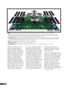
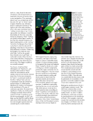
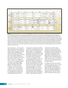
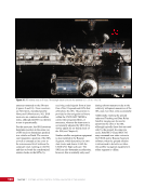
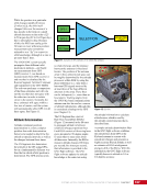
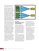
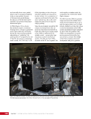
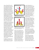
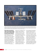
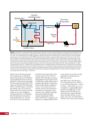
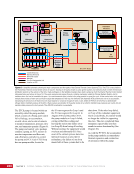
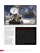
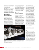
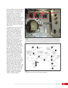
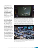
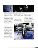
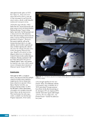
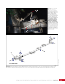
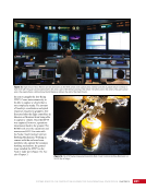
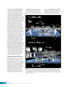
157 SYSTEMS: ELECTRICAL POWER SYSTEM—THE POWER BEHIND IT ALL CHAPTER 9 mechanical joints are used to rotate the solar arrays and even entire truss elements to keep the large USOS solar arrays pointed at the sun. Similar to how transformers on utility poles near homes work, power is then converted to lower voltage in the Secondary Power System for use by end-user devices, or “loads,” such as computers and fans. A series of cables and power distribution units move power throughout the EPS and ultimately to users, as with high-tension power lines, buried cables, and even wiring inside homes. Finally, the EPS contains specific loads that support overall operations on board the ISS, including lights, switches, and extension cords. In summary, the ISS solar arrays collect power during insolation, when the ISS is not in the shadow of the Earth. This power is supplied to equipment throughout the ISS and charges batteries for use during eclipse, when the Earth shadows the ISS from the sun. Power flows through various distribution control devices and switches to reach end- user loads. This chapter will discuss the hardware and process of converting sunlight into useable power and safely distributing it throughout the space station. Although many power systems used on the ISS are similar to those in terrestrial electrical networks and homes, the need for redundancy and the ability to be operated from far away in Mission Control require a number of critical design choices. The massive solar arrays on the ISS demand a great deal of interaction by the flight control team due to a number of constraints on the solar array operations, many of which were imposed after their design, including when and how other vehicles can dock. Background: Design Decisions Distributed vs. Non-distributed Electrical Power System The first ISS modules were designed with non-distributed EPSs. This means each module has a self-contained EPS that is able to generate, store, and distribute electrical power. Each module has its own solar arrays, batteries, distribution network, switches, etc. This structure was essential for early space station modules so that they could be essentially turnkey after launch, thus not requiring assembly or crew tending on orbit. The Russian Functional Cargo Block (FGB) and Service Module (SM) are based on designs used for the Mir space station, where non-distributed EPSs worked well. However, having each module outfitted with its own EPS adds mass, complexity, maintenance, and overall cost. As the ISS grew, new modules would potentially shadow the solar arrays of other modules, thereby causing loss of necessary power generation. In fact, deployment of the External Thermal Control System (ETCS) radiators (see Chapter 11) on the P1 and S1 truss segments physically interfered with the FGB solar array rotational envelope. This required the FGB solar arrays to be retracted, which greatly reduced their power-generation capabilities. The FGB then became dependent on power transfer from the USOS. The USOS EPS and later RS modules were designed using a distributed EPS. Power is generated and stored by specifically designed power modules and then distributed to the rest of the ISS where it is needed. Having dedicated power modules reduces the mass required by having replicated power systems such as batteries and converters for each module. However, this warrants much larger solar arrays and batteries to meet the power demands of the ISS. These large solar arrays were placed farther from other modules, which allowed the arrays to be positioned to see the sun and avoid sunlight blockage from other modules. The design trade was that it would take multiple Space Shuttle missions over the course of years until the USOS Primary Power System would be fully assembled. This meant full capability and redundancy was not available until well into ISS assembly, which resulted in a limiting effect on the amount of science conducted on the ISS early in its lifetime. Additionally, this caused many changes in procedures and training for ground controllers and crew. Almost constant work was required to keep the operations team in sync with the current configuration. Current, Voltage, and Mass Going back to the beginning of the earliest uses of electrical power, arguments took place over the benefits and detriments between alternating current (AC) and direct current (DC). In the 1880s, this became a famous “battle” between Thomas Edison (promoting DC) and George Westinghouse, who held patents to Nikola Tesla’s work with AC. Terrestrially, AC won out due to cost and efficiency, with the United States using a 110 Volt AC system and the European standard 220 Volt AC. However, solar array and battery system designs naturally generate and store energy using DC. In fact, 28 Volt DC systems have become an aerospace industry standard. However, it can be difficult to efficiently change the voltage in a DC system and, as will be discussed later, the ISS
Purchased by unknown, nofirst nolast
From: Scampersandbox (scampersandbox.tizrapublisher.com)