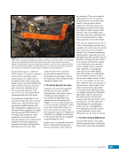
CHAPTER 11 SYSTEMS: THERMAL CONTROL—THE “CIRCULATORY SYSTEM” OF THE INTERNATIONAL SPACE STATION 204 greater than the need. Therefore, some of the flow paths still have their original nitrogen fill and have not yet been used. Figure 8. A major component of the ETCS as seen from the Space Shuttle. The left image shows the port and starboard radiator beams (three radiators per beam, with each radiator consisting of eight panels). On the right is a close-up of the Radiator Beam Truss Structure that is rotated by the Thermal Radiator Rotary Joint to maximize heat rejection. Though the EETCS radiators on the P6 truss were fixed, each set of ETCS radiators can be rotated to improve heat rejection by positioning the radiator beam so that its three radiators are in an edge-to-sun position. This rotation is accomplished via the Thermal Radiator Rotary Joint (TRRJ) (Figure 8), which uses many of the same components as the Solar Array Rotary Joint (SARJ) described in Chapter 9. As with the SARJ, the TRRJ consists of a pair of drive/lock assemblies and a pair of rotary joint motor controllers (see Chapter 9). Unlike the SARJ, the TRRJ has a limited rotational capability because it is impractical to use fluid connectors that have a full 360 degrees of rotation. Instead, the fluid hose rotary coupler provides fluid connections from one end of the TRRJ to the other, and the hoses within the fluid hose rotary coupler limit rotation to 210 total degrees of rotation, 105 degrees in each direction. The TRRJ interface is also much smaller than the SARJ interface. Whereas the SARJ rings are as large as the truss segment that houses it (i.e., large enough for a person to stand inside), the TRRJ is a fairly compact cylinder installed in the center of the S1 and P1 truss segments. Also, unlike the SARJ, the TRRJ generally does not need to rotate very much and can be left in the same position, changing only for specific attitude changes or certain solar beta angles (see Chapter 7). The primary purpose of all three external systems is to cool the heat exchangers that provide heat transfer from pressurized modules. However, the ETCS also supports several EPS components that are located on the truss segments. These electrical components are mounted on an interface known as a coldplate, which both connects the component to the truss and provides an interface for ETCS cooling (Figure 9). Each coldplate is a broad plate with narrow- set fins extending from it. Those fins interleave with fins extending from the electrical component such that heat from the electrical component fins radiates to the coldplate fins. This finned plate is bonded to a stainless steel flow plate, which is sealed to allow ammonia flow through the unit to pick up heat transferred through the aluminum fins. Each ETCS loop provides cooling to five electrical components in addition to five heat exchangers. Though the heat load from the electrical components is a small fraction of the heat load from the heat exchanger, the electrical components are fully dependent on ETCS cooling to function at full capacity. Water in Water out Heat Coldplate Hardware Figure 9. A schematic showing how a coldplate works. Cold liquid flows in from the left side and picks up heat generated by the attached hardware. The warmed liquid then flows out toward the radiators.
Purchased by unknown, nofirst nolast
From: Scampersandbox (scampersandbox.tizrapublisher.com)


