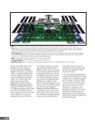
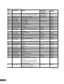
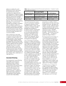
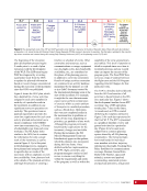
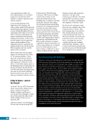
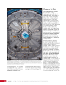
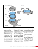
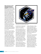
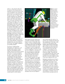
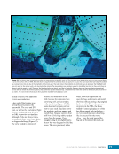
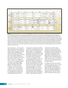
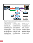
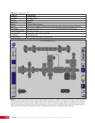
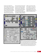
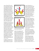
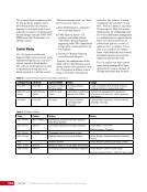
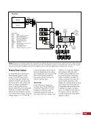
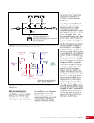
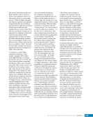
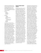
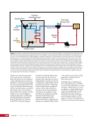
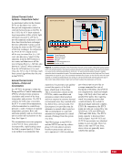
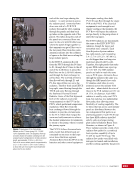
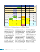
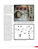
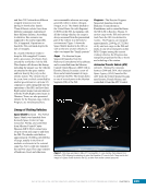
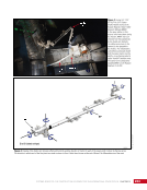
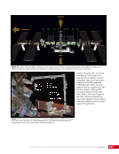
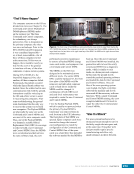
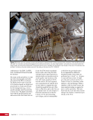
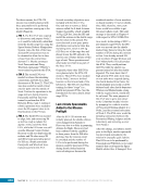
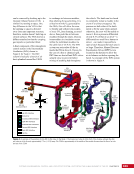
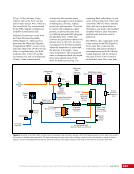
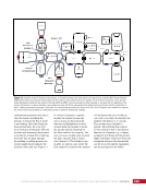
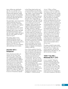
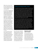
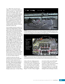
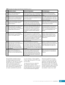
CHAPTER 11 SYSTEMS: THERMAL CONTROL—THE “CIRCULATORY SYSTEM” OF THE INTERNATIONAL SPACE STATION 196 absorb some of the heat generated by the load, thereby warming the fluid. The point in an active thermal system where heat leaves the loop is referred to as the heat rejection point. The heat rejection point for the ITCS loops is an Interface Heat Exchanger (IFHX), which provides a connection point between the ITCS inside the ISS and the ETCS outside of the ISS (Figure 2). In a heat exchanger, a warm fluid passes by a colder fluid, thus allowing heat to be rejected from the hot side to the cold side. In the ETCS, the heat exchanger provides the heat load, and the heat rejection points for the ETCS are radiators that radiate heat into space. Pump hardware in each type of loop circulates the coolant (either water or ammonia) through the cooling loop. Each cooling loop has a number of sensors, valves, and controllers to maintain desired loop temperatures and monitor for problems in loop operation. The cooling loops inside and outside the ISS use many common components, but the details of how those components are designed or configured differs based on the specific needs of the cooling application, as discussed in the following sections. Bypass Valve Isolation Valve From Radiator Bleed Line Three Way Mixing Valve Outlet Flow Bypass Flow Inlet Flow Pump To Radiator Interface Heat Exchanger M Heat Loads Figure 2. A schematic of an ATCS. Warm water (red) flow starts at the pump in the lower right of the diagram. Coolant passes into the IFHX where it will pass heat to the colder ammonia (blue then yellow) inside the heat exchanger. The now-cooled water (pink then blue) flows back to the loads to pick up more heat. The Three Way Mixing Valve (TWMV) is adjusted to regulate the temperature of the fluid going to the loads at the upper right of the diagram. Some warm fluid can be pulled directly into the TWMV, bypassing the heat exchanger, to make sure the fluid going to the loads is not too cold. On the left of the diagram, cold ammonia (light blue) comes into the heat exchanger from the radiators. Inside the heat exchanger, the ammonia picks up heat from the water such that it leaves the IFHX warmer (yellow) and returns to the external pump (not shown), which will push it back to the radiators again. A bypass valve will divert the flow of ammonia away from the heat exchanger when it is not being used. An isolation valve, in conjunction with the bypass valve, can be used to isolate the heat exchanger and prevent colder-than-normal ammonia from reaching the center of the heat exchanger. This might be needed during repair work, for example. The heat exchanger cannot be completely isolated from the ammonia side of the system due to the presence of what is known as a bleed line. When a heat exchanger is isolated, there is a risk that the ammonia remaining in the heat exchanger could get hot and increase in pressure. The bleed line provides a pressure relief capability, allowing ammonia to safely escape the heat exchanger if it heats up. The “M” in a circle over some valves indicates a manual override, which means an astronaut could adjust that valve if, for some reason, the computer control was not working properly. See also Figure 2 in Chapter 20. Each fluid loop on the ISS uses a Three Way Mixing Valve (TWMV) to control loop temperature, as shown in Figure 2. These three-way valves are similar to a single-handle faucet control at a kitchen sink. As with kitchen faucets, these three-way valves have two sources of liquid that are blended together into one outlet. One source of coolant flow at TWMV comes from the heat rejection
Purchased by unknown, nofirst nolast
From: Scampersandbox (scampersandbox.tizrapublisher.com)