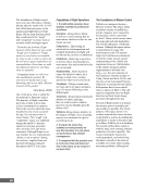
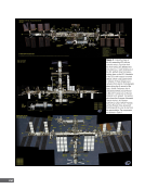
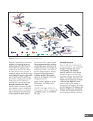
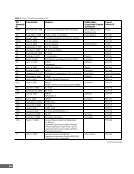
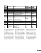
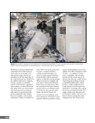
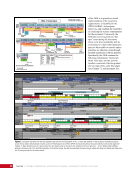
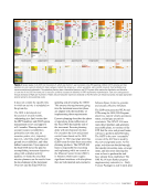
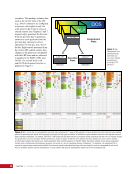
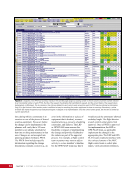
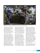
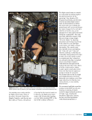
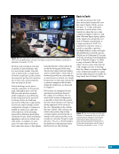
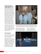
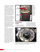
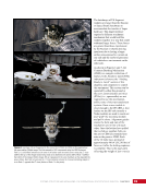
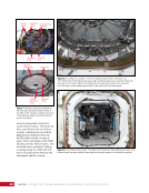
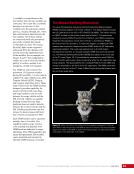
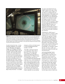
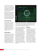
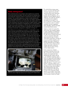
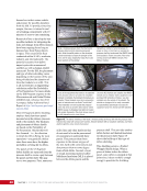
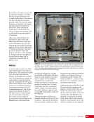
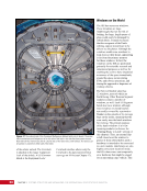
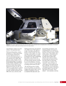
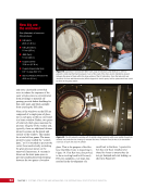
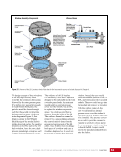
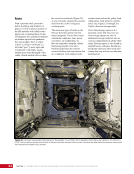
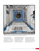
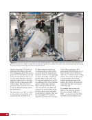
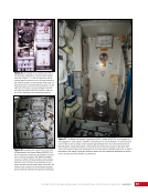
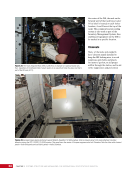
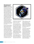
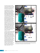
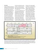
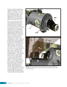
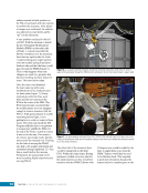
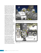
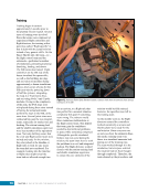
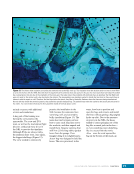
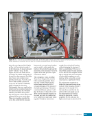
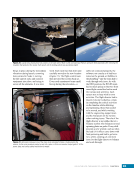
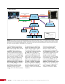
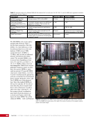
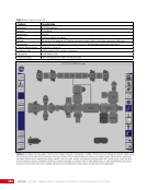
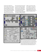
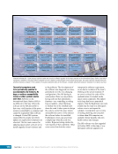
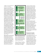
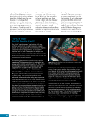
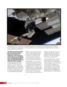
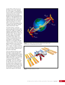
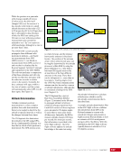
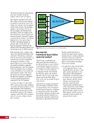
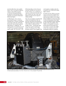
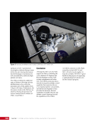
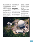
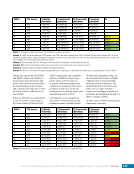
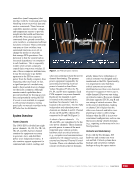
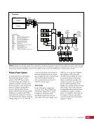
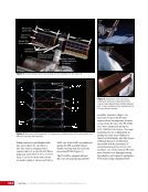
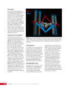
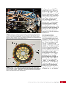
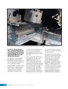
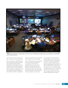
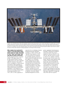
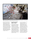
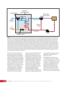
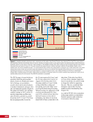
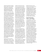
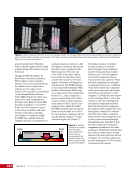
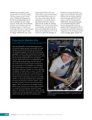
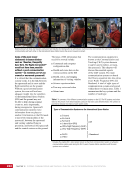
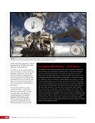
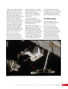
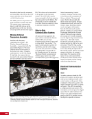
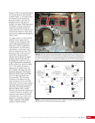
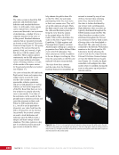
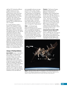
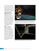
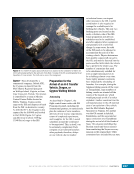
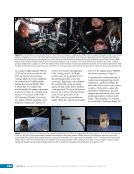
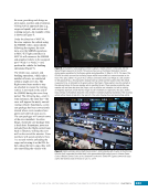
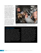
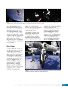
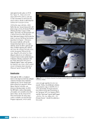
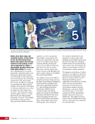
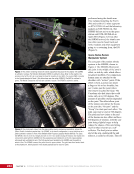
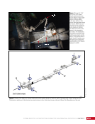
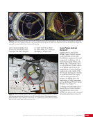
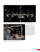
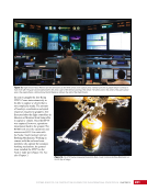
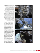
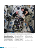
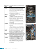
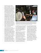
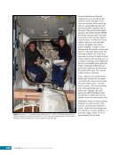
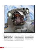
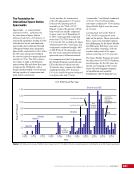
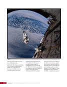
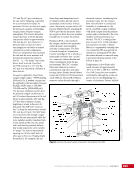
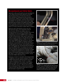
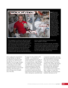
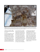
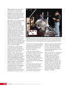
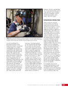
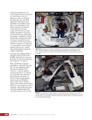
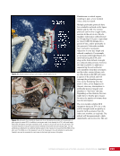
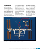
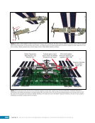
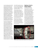
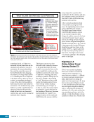
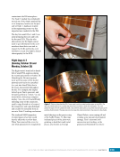
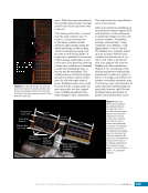
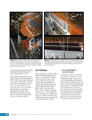
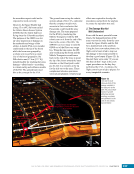
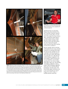
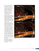
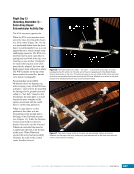
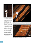
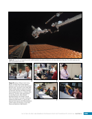
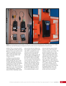
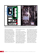
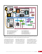
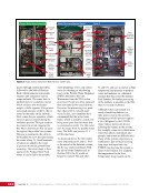
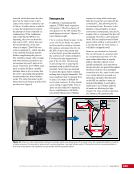
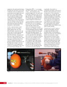
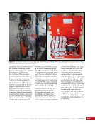
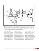
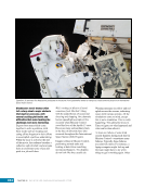
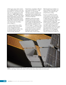
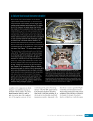
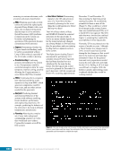
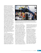
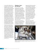
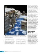
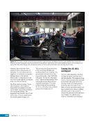
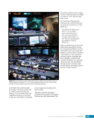
CHAPTER 15 SYSTEMS: ROBOTICS—THE CONSTRUCTION EQUIPMENT FOR THE INTERNATIONAL SPACE STATION 254 joints cannot be offset with anything however, as with the other joints, they have 540 degrees of motion. A large black stripe is located on one of the booms (Boom B) since either end can be fixed to structure while the other end is used to manipulate an object. The boom at the other end is referred to as Boom A. Four cameras—one at each end and two at the elbow (not shown)—allow the operator to see what is being grappled and help prevent collisions between the arm and structure. One of the most critical parts of the arm is the Latching End Effector (LEE). A LEE is located on each end of the arm. One LEE allows the arm to grab payloads while the other acts as “base” for the arm when attached to the space station (Figure 5). The LEE is similar in size and shape to a barrel with the lid removed. Four latch mechanisms, an attachment point of an extravehicular activity (EVA) boot plate that allows an astronaut to attach to the arm (See Chapters 17 and 18), and a camera with a light are all situated around the outside of the LEE. Latches (4) EVA Attach Point 80 cm (31 in.) Light (Camera is hidden) Figure 5. A LEE. The lights on top of the camera are to the right in this image. The EVA attach point allows a spacewalking astronaut to attach a foot restraint, attach his or her boots, and “ride” the arm (see Chapters 17 and 18). The snare cables in this image are completely open and fit flat against the opening. Grabbing or attaching payloads is accomplished using a combination of snares and latches. The snares are braided wire ropes on a rotating ring. When the inner ring is rotated, the snares form a web across the open end of the LEE (Figure 6). To capture a payload, the snares close across a metal rod called a grapple shaft on the grapple fixture. An operator maneuvers the LEE so that the grapple shaft is inside the open cavity of the LEE. The snares close around the grapple shaft and a semisphere on top of the pin prevents the rod from sliding out of the snares. The three lobes (Figure 7) in the grapple fixture align with the indentations of the LEE, thereby allowing the arm to snuggly align to the base of the grapple fixture. The arm has a strong hold on the payload once the carriage has retracted and the back plate of the grapple fixture is tight against the face of the LEE. Some grapple fixtures (Figure 7) have additional features that the SSRMS can latch onto, which can provide power and data. This special type of grapple fixture is called a Power and Data Grapple Fixture (PDGF). Behind four small, spring- loaded doors are electrical, data, and video connections. A PDGF also has an outer ring on the baseplate. This outer ring is composed of many small teeth called a curvic coupling. A matching set of teeth are located on the LEE (Figure 5). As a PDGF is grappled, the curvic coupling enables precise alignment between the LEE and the grapple fixture, thus allowing for various service connections to be made. When the arm grapples a PDGF, umbilicals are extended from the LEE, which will pass through the protective doors and connect to power, data, and video. The ability to provide power, data, and video through a PDGF to the arm is major component of the mobility in the MSS. Several PDGFs are positioned around the ISS. These PDGFs, coupled with the LEEs, allow the SSRMS to reach worksites that a fixed robotic arm could not. The arm is connected to a PDGF at both ends to change locations. One end is then released and moved to another PDGF. This
Purchased by unknown, nofirst nolast
From: Scampersandbox (scampersandbox.tizrapublisher.com)