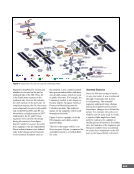
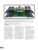
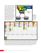
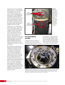
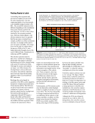
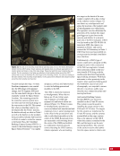
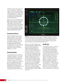
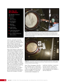
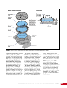
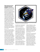
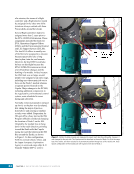
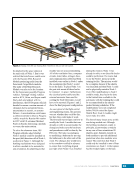
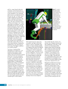
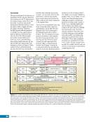
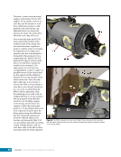
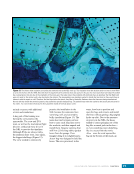
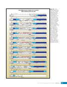
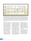
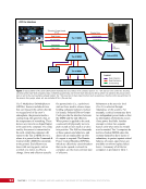
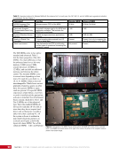
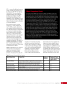
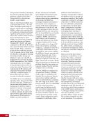
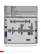
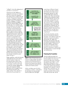
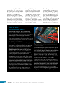
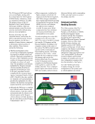
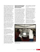
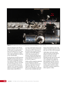
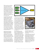
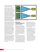
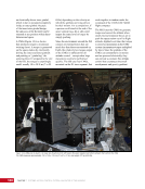
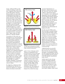
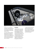
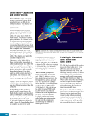
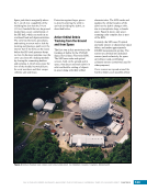
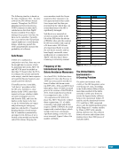
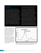
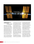
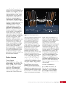
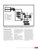
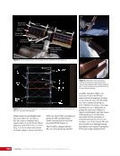
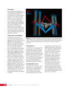
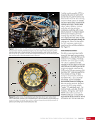
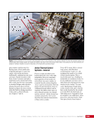
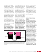
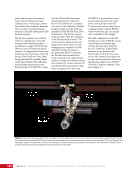
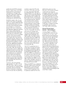
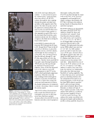
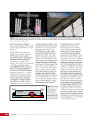
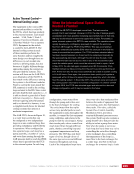
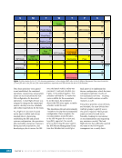
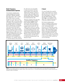
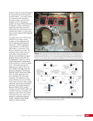
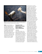
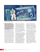
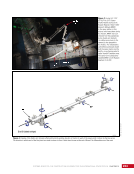
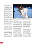
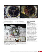
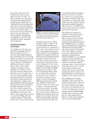
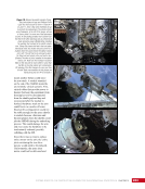
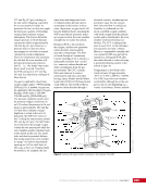
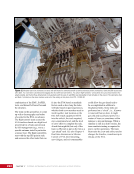
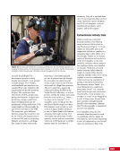
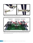
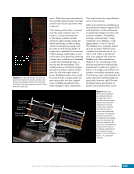
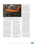
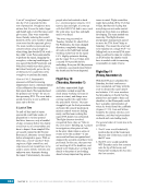
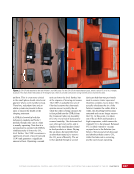
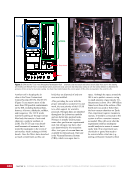
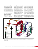
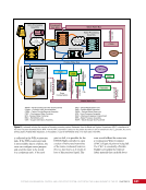
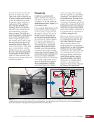
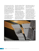
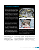
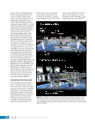
CHAPTER 9 SYSTEMS: ELECTRICAL POWER SYSTEM—THE POWER BEHIND IT ALL 168 Power Buses Power buses provide the physical mounting structure for Remote Power Control Modules (RPCMs) and provide access to command and data interfaces, power input and output connections, and cooling. They do not have any active components (i.e., no moving switches or gears) and only provide structural, thermal, power, and data support for RPCMs. The number of RPCMs in each power bus varies depending on power requirements in that particular location of the vehicle. Power buses were not designed to be replaceable and can be found both internally and externally on the ISS. Remote Power Control Modules The RPCMs are the interface between the EPS and all non-EPS equipment on board the ISS. Because RPCMs are the most numerous EPS devices on the ISS, and due to their direct interface to downstream loads, the crew and ground have the most interaction with these items. The distribution of secondary power to downstream loads can be controlled by opening and closing RPCs within the RPCMs. Protection of the EPS against downstream faults is accomplished by opening RPCs when too much current draw is detected. The RPCMs come in six different configurations, each with a different number of RPCs with different current ratings and current- limiting capabilities. The type of RPCM used in any particular location depends upon the downstream load requirements. All RPCMs have the same housing and the same standard interface connectors, and can be located either externally or internally to the ISS. Pointing Systems To maximize the power generated by the solar arrays, the USOS EPS was designed with multiple articulating joints to allow the solar arrays to be rotated to point at and track the sun as the ISS orbits the Earth. Two separate kinds of rotary joints are used to position USOS solar arrays (Figure 8), due to the changing alpha and beta angles and the potential need to change ISS attitudes (see Chapter 7). SARJs ß ß ß ß ßß ß ß α α BGAs BGAs Rotation SARJs Rotation Figure 8. US Segment solar array angle rotation showing the rotation of the SARJ and the Beta Gimbal Assembly (BGA), as indicated. The BGAs allow the arrays to compensate for the β angle (see Chapter 7, Figure 7), which changes slowly over the year. The SARJ nominally rotates 360° as the space station rotates around the Earth to always keep the solar cells facing the sun. This angle is called the “α” (alpha) angle. Solar Alpha Rotary Joints The SARJs rotate the PVMs—entire truss segments—to provide alpha angle array pointing capability (i.e., when the ISS is in the nominal +XVV attitude). The port and starboard SARJs are located at the outboard end of the P3 and S3 truss segments, respectively, and provide 360° continuous rotational capability to the segments outboard of P3 and S3. The rotary joints normally complete one 360º revolution during each 90-minute orbit of the ISS around the Earth. Essentially, the SARJs are large gears rings with supporting bearings and drive motors. Each SARJ features two redundant control strings, one powered from each power domain. Each string consists of firmware controllers that include sensors to monitor the position and rotational speed of the SARJ, along with drive/ lock assemblies that house the motor, gear teeth, and locking racks used for positioning. See Figure 9.
Purchased by unknown, nofirst nolast
From: Scampersandbox (scampersandbox.tizrapublisher.com)