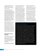
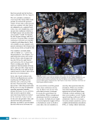
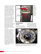
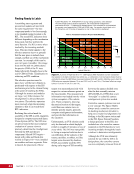
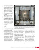
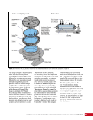
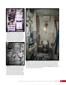
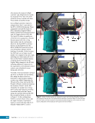
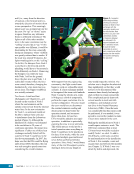
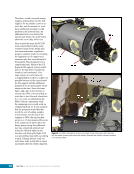
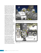
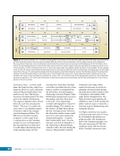
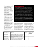
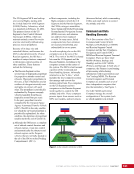
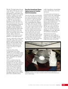
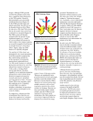
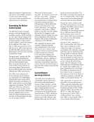
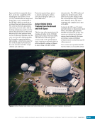
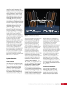
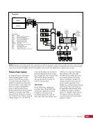
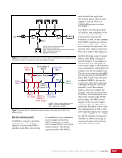
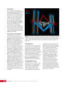
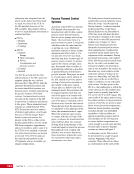
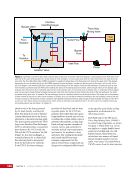
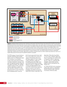
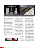
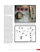
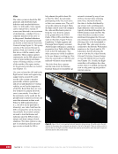
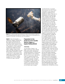
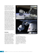
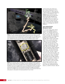
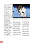
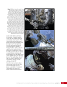
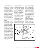
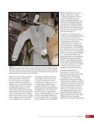
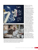
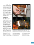
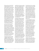
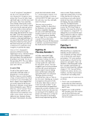
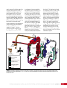
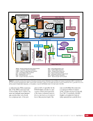
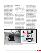
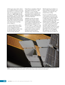
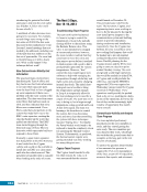
197 SYSTEMS: THERMAL CONTROL—THE “CIRCULATORY SYSTEM” OF THE INTERNATIONAL SPACE STATION CHAPTER 11 point in the loop and provides the coldest fluid in the loop. This source is comparable to the water coming from the water main into the kitchen. The second source comes from a line that bypassed the heat rejection point and is still warm. This source is similar to the water coming from the water heater, but instead of being intentionally warmed, it is warm from the heat loads on the ISS. The two sources are known as the return line and the bypass line, respectively, and the valve position determines how much of the warm bypass line coolant is added to the cold return line coolant in the outlet line. In the three external cooling loops, these valves are called Flow Control Valves (FCVs). Three-way valves are also used to provide control of loop pressure at some points in the ITCS, as will be discussed later in the ITCS section of this chapter. The active systems use one or more accumulators to manage loop pressures. Accumulators serve three purposes in ISS fluid loops: they allow for thermal contraction and expansion of the cooling fluid, ensure sufficient pressure at the inlet to each fluid system pump, and provide a small amount of makeup fluid in the event of a fluid leak. An accumulator is a small tank with a compressible metal bellows inside (Figure 3). A bellows is an accordion-like container that is able to expand and contract freely. On the ISS, the tank usually contains the cooling fluid and the bellows contains nitrogen at a desired pressure. Since the bellows is free to expand and contract, the pressure of the coolant will match the pressure of the nitrogen therefore, the nitrogen pressure is used to control and maintain the pressure of an entire cooling loop, through the accumulator. Ammonia Bellows expanded Bellows compressed Nitrogen Gas Ammonia Figure 3. The accumulator for the Pump Flow Control Subassembly is illustrated, but the other TCS accumulators work on the same principles. Fluid (in this case, ammonia) is in the tank surrounding the orange bellows, which can expand and contract. Nitrogen gas within the bellows provides pressure on the bellows, which in turn applies pressure to the ammonia to help ensure it can move around the system properly. After detailed engineering analysis, NASA chose ammonia as the coolant for the ATCSs on the exterior of the space station for several reasons: ammonia has a lower density than many other commercially available coolants and can therefore be launched in great quantity at dramatically reduced launch costs it has a low viscosity so it requires little power for pumps to circulate the ammonia through cooling loops and ammonia remains liquid down to -78°C (-108°F), which is important in the extreme cold of the ISS external environment. On the downside, ammonia is toxic to humans therefore, the possibility of this dangerous chemical leaking into the pressurized cabin is one of the three major emergency responses discussed in Chapter 19. Active Thermal Control— External Thermal Cooling Systems The ETCS expanded significantly throughout construction of the space station, though the fundamental design of the system remained the same. These systems have been critical to human presence on the ISS. Without the ability to reject heat from the interior of the ISS overboard, the many systems inside the station cannot operate for long without the air becoming unbearably hot. The challenge during assembly of the ISS was that the large, permanent ETCS loops would not arrive until the latter half of the construction sequence. The ammonia loops arrived already integrated into the truss segments that make up the backbone of the ISS, providing structure and infrastructure for power to flow from the outboard solar arrays into the central core of the station. Many of the habitable modules of the ISS arrived years before the truss was completed, but they could not be fully activated until the permanent thermal and power systems arrived with the trusses. The assembly sequence was altered to provide one truss segment, P6, early in the sequence, with a pair of solar
Purchased by unknown, nofirst nolast
From: Scampersandbox (scampersandbox.tizrapublisher.com)