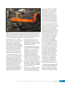
201 SYSTEMS: THERMAL CONTROL—THE “CIRCULATORY SYSTEM” OF THE INTERNATIONAL SPACE STATION CHAPTER 11 module when the ETCS is dormant. Pressure control of the ETCS loops during operation is provided by a combination of a Nitrogen Tank Assembly (NTA) and an Ammonia Tank Assembly (ATA), which together act as a large ammonia accumulator for each ETCS Loop. The ETCS contains 118 L (31 gal.) in each of two loops. As mentioned above, any segment of fluid line filled with ammonia must have access to a pressure relief mechanism, usually an accumulator or a mechanical pressure relief valve, to ensure that rapid ammonia temperature increases do not cause overpressurization, which could burst lines. Because the ETCS loops were launched to orbit in many sections across several flight elements, each section was filled with nitrogen rather than ammonia. Using inert nitrogen, which does not respond to temperature extremes with the same pressure changes to which ammonia is susceptible, prevented the need for additional accumulators throughout the system. Once the entire system had been assembled on the ISS in 2006, the nitrogen was vented and the system was filled with ammonia just prior to activation. This strategy allowed all of the ammonia to be contained in a set of ammonia tanks for launch and installation therefore, the cost of overpressure protection was limited to the design of those ammonia tanks, which were then incorporated into the ETCS as part of the ATA. The ATA is a box that measures approximately 175 x 102 x 137 cm (69 x 40 x 54 in.). The box consists of the following: two ammonia tanks an isolation valve for each tank pressure, temperature, and quantity sensors for each tank the plumbing needed to connect the ATA to the rest of the ETCS and a vent valve on a line connected to both tanks. Each ATA holds 397 L (105 gal.) of ammonia. Each of the ATA ammonia tanks includes a bellows filled with pressurized nitrogen, such that each tank is able to act as an accumulator, accommodating thermal expansion and contraction of the ammonia, pressurizing the loop for optimal pump performance, and providing ammonia to make up for leakage over time. The nitrogen side of the ATA is connected to the NTA, a box that measures approximately 152 x 91 x 76 cm (60 x 36 x 30 in.) and consists of a nitrogen tank, pressure and temperature sensors, a Gas Pressure Regulating Valve (GPRV), and two isolation valves. The plumbing in the NTA connects the nitrogen tank to the GPRV. The plumbing then splits into two lines (one connecting to each tank in the ATA), each with an isolation valve that can cut off the NTA from the associated ATA tank. The PVTCS accumulators have a fixed charge of nitrogen that cannot be changed or replenished, whereas the nitrogen pressure in the ATA can be adjusted using the GPRV in the NTA. The GPRV is a combination of four separate valves that can be used to increase or decrease the pressure of the nitrogen that is fed to the ATA tanks. Therefore, the GPRV is used to add or remove nitrogen to increase or decrease, respectively, the pressure in the ammonia lines as needed. Whereas the EETCS was a temporary and fairly simple system with pumps that operated at a fixed speed, the ETCS pump operates at variable speeds so that its capability could be adjusted as additional lines were added to the system over time. When the ETCS was first activated, it connected only to the heat exchangers on the LAB. Over time, as additional modules were added to the ISS, additional ETCS lines were added to provide access to the heat exchangers on those modules, which required additional capability from the pump. The ETCS pumps can operate between 11,250 and 18,000 rpm, as required to provide a system flow rate of 3,719 to 4,037 kg/hr (8200 to 8900 lb/hr). External Thermal Control Systems—Heat Exchangers As seen in Figure 2, an IFHX is an assembly that consists of a heat exchanger core, two valves, three heaters with associated temperature sensors (not shown), and four fluid connectors to connect the heat exchanger to water inlet and outlet lines and ammonia inlet and outlet lines. The heat exchanger core uses a counterflow configuration, with ammonia and water that flow in opposite directions in adjacent layers. Each layer uses a ruffled fin material (i.e., stainless steel for the ammonia layers and nickel for the water layers) separated by a stainless steel parting sheet to keep the fluids separated. The ruffled fins help hold the parting sheets together and provide additional surface area to increase heat transfer. There are two heat exchanger core configurations: one rated to transfer up to 14 kW of heat the other rated for up to 12 kW of heat transfer. Of the 10 heat exchangers on the ISS, eight are the 14 kW design and two are the 12 kW design. Chapter 4 discusses some of the challenges of working with the heat exchanger units on the Node 3 module.
Purchased by unknown, nofirst nolast
From: Scampersandbox (scampersandbox.tizrapublisher.com)


