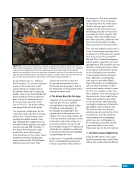
39 SYSTEMS: STRUCTURE AND MECHANISMS—THE INTERNATIONAL SPACE STATION’S SKELETON CHAPTER 3 The hatchways of US Segment modules are larger than the Russian or Space Shuttle hatchways to accommodate the transfer of larger hardware. This larger interface required a different attachment mechanism that would hold the modules together in a way that could withstand larger forces. These forces are greater than those experienced by the Russian or shuttle docking interfaces due to having a larger surface area exposed to vacuum on one side and the sea-level pressures of a shirtsleeve environment on the other side. Figure 6. Top image: ISS as it appeared to the crew of STS-92/ISS-3A (2000) as they approached the space station. Middle image: The first assembly of ISS components using the CBM. Astronaut Peter J. K. (Jeff) Wisoff monitors as the crew of the orbiter uses the robotic arm to bring the Z1 truss (CBM at the top of the image) toward being ready to be latched by the active CBM of Node 1 (CBM at the bottom of the image). Bottom image: ISS as it appeared to the crew members as they departed the space station. Note that not only was the Z1 truss installed, but also the Pressurized Mating Adapter 3 on to Node 1, opposite the Z1 truss (bottom of Node 1 in this photo). As shown in Figures 6 and 7, the Common Berthing Mechanism (CBM) is a complex collection of latches, bolts, Ready to Latch (RTL) indicators (reference the “Finding Ready to Latch” section of this chapter), and computers to control this equipment. This system can be operated by either the ground or the crew extravehicular activities (EVAs) (i.e., spacewalks) are not required to use this mechanism, unlike some of the truss attachment systems. Once a new module is close enough to the ISS (RTL), four latches on the ISS side (usually a Node module) are used to reach out and “grab” the incoming module and pull it closer. Alignment guides ensure the bolts and nuts of the mechanism are in line with each other. Once the latches have pulled the two halves together, bolts on the active CBM are extended into nuts on the passive CBM. Each of the 16 bolts has a preload of approximately 90 kN (20,230 lbs) of force on it after the bolting sequence is complete. That is the equivalent of having the weight of just over six
Purchased by unknown, nofirst nolast
From: Scampersandbox (scampersandbox.tizrapublisher.com)


