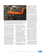
339 SYSTEMS: ENVIRONMENTAL CONTROL AND LIFE SUPPORT SYSTEM—SUPPORTING THE HUMAN ELEMENT OF THE ISS CHAPTER 19 can be removed by hooking up to the Vacuum Exhaust System (VES)—a similar line running to space. One key difference in the VES is that the opening to space is directed away from any important structure therefore, residue doesn’t build up on critical surfaces. The VES also has a diffuser attached so that the escaping gas imparts no particular thrust. A final component of the atmospheric control system is the Intermodular Ventilation (IMV) shown in Figure 4 for Node 2. The IMV system is basically a bunch of air ducts plumbed around the USOS to exchange air between modules, thus allowing for good mixing. It is critical to mix the O 2 generated by the OGA this will allow the crew to breathe and will prevent pockets of toxic CO 2 from forming, as noted above. Fans push the air between modules through the ducts, whereas intramodular air circulation occurs within the individual modules via the cabin fan or CCAAs. The IMV system can recirculate all the air inside the ISS in about 2-3 hours. In the case of a fire or chemical spill, IMV fans are shut off and IMV valves actually close to prevent further mixing of anything bad throughout the vehicle. The hatch can be closed to completely isolate a module in the event of a serious emergency. The pressure on both sides of the hatch needs to be the same when opened otherwise, the crew will be unable to move it. Even a pressure differential of only 0.3% of that at sea level—a differential too small for a human to detect—can make it impossible to open a hatch because the hatch area is so large. Therefore, Manual Pressure Equalization Valves (MPEVs) are located on the hatches to allow the air to balance out before opening the hatch. An example of the IMV system is shown in Figure 4. Lab IMV Interface Node 2 Air Columbus IMV Interfaces JEM IMV Interfaces Overhead IMV Interfaces Forward IMV Interface Deck IMV Interface Inactive IMV Aft Starboard Valve IMV Aft Port Valve IMV Starboard Aft Valve IMV Starboard Forward Valve CCAA Fan Assembly IMV Port Aft Valve IMV Overhead Forward Valve IMV Port Forward Valve IMV Deck Forward Valve IMV Deck Aft Valve IMV Forward Port Valve IMV Forward Starboard Valve IMV Overhead Aft Valve Nadir Zenith Aft Starboard Port Forward Figure 4. An example of the plumbing for the IMV. In this case, for the Node 2. The forward port valve is at the front of the module, whereas the after port valve is at the far end, approximately 7.2 m (~24 ft) away. The CCAA is approximately in the middle of the module. Arrows show the flow of air into and out of the CCAA.
Purchased by unknown, nofirst nolast
From: Scampersandbox (scampersandbox.tizrapublisher.com)


