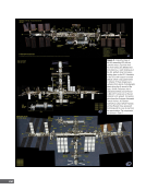
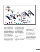
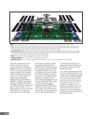
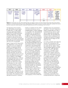
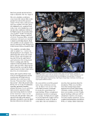
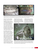
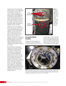
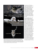
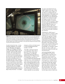
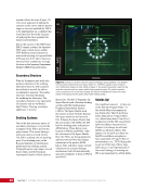
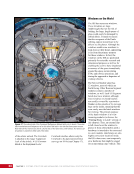
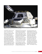
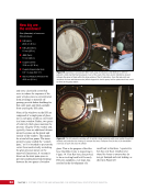
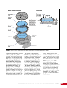
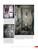
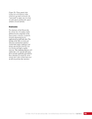
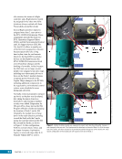
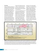
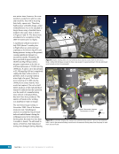
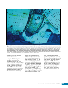
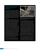
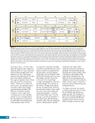
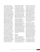
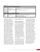
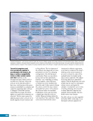
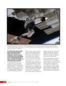
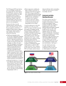
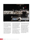
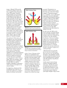
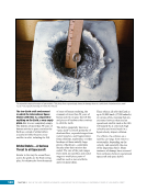
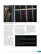
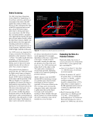
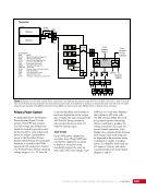
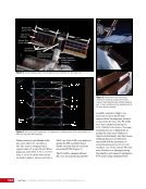
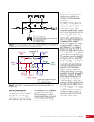
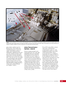
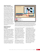
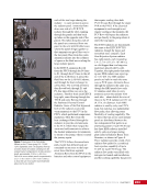
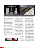
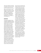
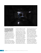
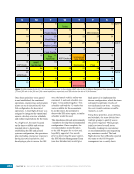
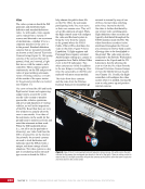
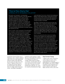
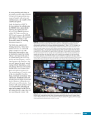
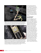
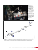
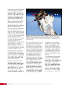
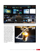
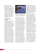
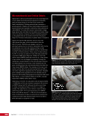
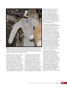
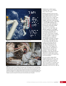
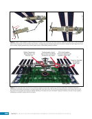
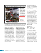
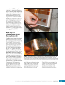
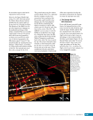
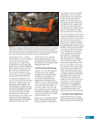
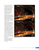
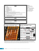
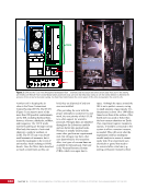
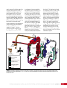
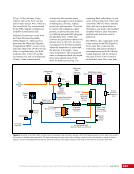
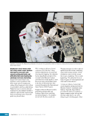
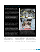
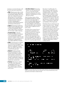
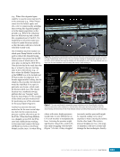
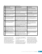
317 DAY IN THE LIFE: RISKY AND REWARDING SPACEWALKS—SPACE SHUTTLE MISSION STS-120/ISS-10A CHAPTER 18 the accordion aspect could not be expected to work correctly. However, the Space Shuttle had a long 15 m (49.2 ft) boom called the Orbiter Boom Sensor System (OBSS) that the shuttle had been flying since the Columbia accident. The purpose of the OBSS was for up-close inspection of damage on the underside and wings of the orbiter. A shuttle EVA crew member could stand on the tip of the boom while the boom was grasped by a robotic arm to perform a repair. Use of the boom grasped by the ISS robotic arm (17.6 m [57.7 ft]) looked feasible for reaching the array damage—albeit barely—according to virtual reality and software models of the ISS. The ground team used this as the concept for the EVA. The ground team set up the robotic systems ahead of the EVA, optimistic that the computer models were accurate in their conclusion that Parazynski could reach the array damage site. The team prepared for the EVA by translating the Mobile Transporter with the ISS robotic arm on it from the end of the truss to the center of the ISS. The SSRMS was now ready to take the OBSS out of the Discovery cargo bay. When the time came, the ISS arm would grasp the boom and the Mobile Transporter would move back to the end of the truss to point the tip of the boom toward the truss structure so that Parazynski could put his feet in a restraint at the tip for the ride out to the array. These complicated robotics operations were not pre-planned. A fairly large effort was required to develop the procedures and perform the analysis to ensure the operation was safe. 2. The Damage Was Not Well Understood Even with the most powerful zoom lenses, the damaged portion of the array was too far away from the crew inside the Space Shuttle and the ISS for a detailed look at the problem. Using the best crew-taken photos, the flight control team tried to map out the damage to the extent possible to develop a good repair (Figure 12). In the end, there were some “if you see this then do that” steps in the crew repair procedures on the day they performed the EVA. As always, the flight control team tried to prepare for every imaginable scenario. Upper Blanket Box Lower Blanket Box Panel 37 Panel 38 Panel 36 Panel 35 Panel 34 Large Damage Hinge Loops and Doubler – Hinge Wire is inside the Doubler ~ 8–12 inches Small Damage Hinge Wire from Lower Hinge (sketched in) ~ 8–12 inches Location of Grommets Guide Wire Stbd Port Figure 12. This was the best close-up photo of the damage available in the days prior to the EVA. The ground team marked it up with white lines and red markings, as shown, and uplinked it to the crew in this training documentation.
Purchased by unknown, nofirst nolast
From: Scampersandbox (scampersandbox.tizrapublisher.com)