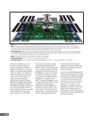
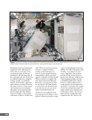
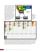
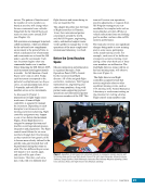
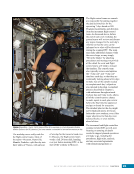
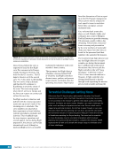
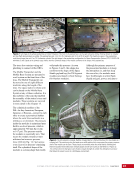
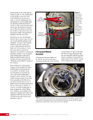
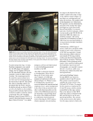
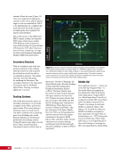
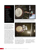
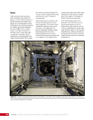
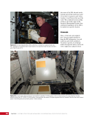
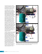
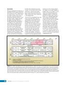
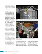
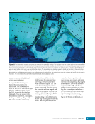
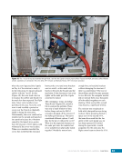
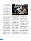
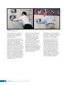
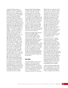
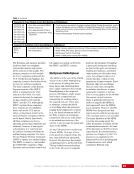
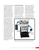
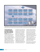
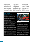
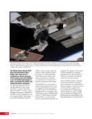
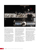
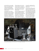
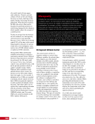
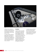
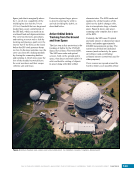
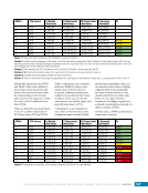
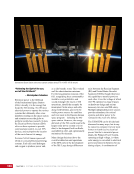
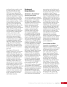
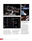
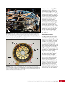
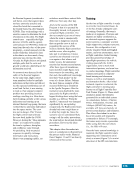
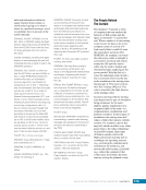
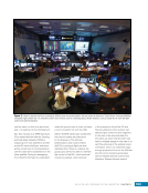
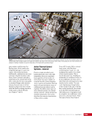
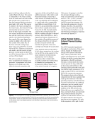
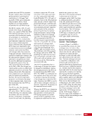
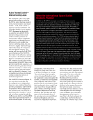
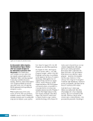
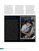
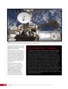
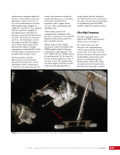
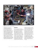
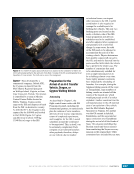
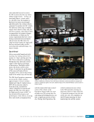
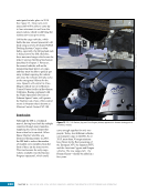
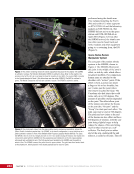
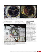
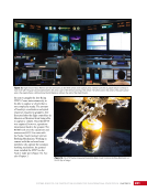
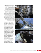
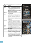
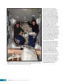
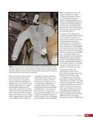
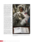
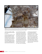
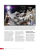
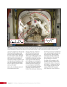
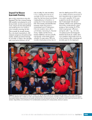
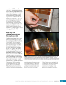
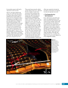
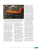
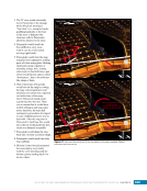
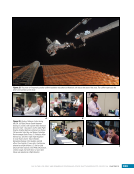
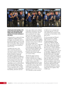
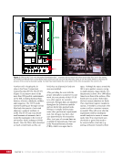
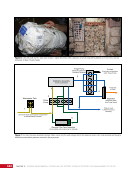
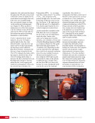
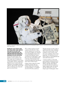
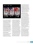
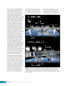
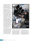
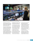
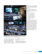
55 SYSTEMS: STRUCTURE AND MECHANISMS—THE INTERNATIONAL SPACE STATION’S SKELETON CHAPTER 3 Figure 23. A view of the JEM from its Airlock looking starboard toward Node 2 and Columbus. The camera taking this photo would be in Bay 7 of the JPM. The JPM1F2 location would be the second rack bay from the hatch on the forward wall (which is to the left in this picture). That means it would be the rack bay covered by the white fabric panel on the left side of the image, second rack bay from the blue wall/hatchway. The rack concept for the US Segment hearkens to similar concepts in use in laboratories and research facilities on Earth. Using standard interfaces—i.e., interfaces between rack and module as well as those inside each rack—allow for relatively simple and straightforward interchangeability of avionics and research experiments throughout the US Segment. Each rack on the ISS is held to the structure of its ISS module by four points—one at each corner of the front of the rack. As shown in Figure 23, spaces exist between the top of one rack and the bottom of the next. Lights, ventilation grids, power outlets, and other equipment are installed in these areas of each module. These standoff areas are also where the racks
Purchased by unknown, nofirst nolast
From: Scampersandbox (scampersandbox.tizrapublisher.com)